In the continuing process of semiconductor companies buying each other up, ON Semiconductor has acquired Fairchild Semiconductor for $2.4 Billion.
ON Semi and Fairchild’s deal is only the latest in a long line of mergers and acquisitions. We’ve recently seen Dialog’s buyout of Atmel, Avago’s purchase of Broadcom, NXP and Freescale’s merger, and soon might see TI buy Maxim. We’re currently in the great time of acquisition, with nearly $100 Billion flowing from company to company in just a few months.
Companies have cash to spend and costs to cut. This latest deal is expected to save $150 Million in annual costs.
Fairchild has a long and storied history in the semiconductor industry, with the first integrated circuit produced in a Fairchild lab in Palo Alto. [Bob Widlar] made Fairchild his home until famously leaving for National Semiconductor in 1965. Somewhat ironically, Fairchild Semiconductor was bought by National Semiconductor in 1987.
ON Semiconductor’s history is not nearly as interesting, being spun off of Motorola’s semiconductor business in 1999. Although ON’s main line of business was discrete components, ON also has a catalog of quite a few power management ICs.
Unfortunately, because ON Semi bought Fairchild and not the other way around, we’re stuck with what is probably the worst logo in the entire semiconductor industry: drop-shadowed balls are so mid-90s!

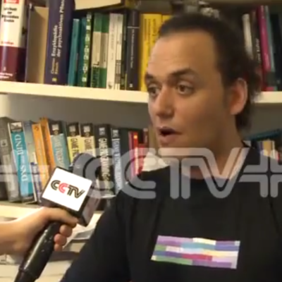 Wanting to send a message to at least a few people in China, the members of the hackerspace had to think laterally. Metalab member [amir] came up with a way to encode data that could be printed on t-shirts. These bright, colorful squares featured in all of the interviews with Metalab members carried messages like, “free tibet!”, “remember tian’anmen 1989” and “question the government. dont trust the propaganda”