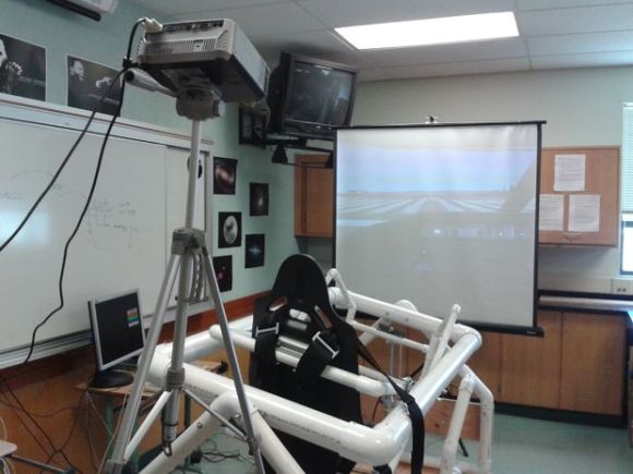
Hacking And Philosophy: The Mentor’s Manifesto

hnpMentorsManifesto

Welcome back to Hacking & Philosophy! I’ve done my best to keep up with the comments from last week’s article, and your responses and suggestions have been invaluable. Most readers expressed concern over how this column would define “hacker” or “hacking,” and whether the texts focused more on hacking-as-illegal or the hacker/maker culture. Rest assured that all interpretations are welcome, but I have no intention of dwelling on the sensationalized, criminal hacker stereotype, either. Others asked whether we’d be holding our conversation somewhere a bit more user-friendly: a solution is in the works. For now, we will stick to the comments.

Last week, I asked you to read an early document in hacking history: The Mentor’s “A Hacker Manifesto,” also called “The Conscience of a Hacker.” What follows is my analysis of the essay. I invite you to join me in a discussion in the comments: post your responses to the piece, your questions, your objections, anything! Now, lets take a trip back to the 80’s…

Continue reading “Hacking And Philosophy: The Mentor’s Manifesto”

HHH: CNC Winners

hhh-cnc-winners

Congratulations to the winners of the first Hackaday Hackerspace Henchmen series. We asked hackerspace members to send us stories about CNC hacks. Here’s a roundup of the three winners:

[Rich] from the Connecticut Hackerspace gets the top spot having sent in the story of their desktop CNC mill hacks. He gets a $50 gift card to the parts vendor of his choosing.

[Barnaby] is also a winner for sharing the story of how they hacked a script to translate G-Code into the proprietary format accepted by the desktop CNC mill at rlab.

And [Tim’s] submission showed how a movable storage base was built for the CNC carving machine at The Rabbit Hole.

We had hoped for more entries and planned to send out stickers to all and shirts to the top five. We’ll be sending both shirts and stickers to the three winners. We’re undecided as to whether we should continue the HHH program with a new theme. We’d love to hear what you think about it in the comments section.

ASAP 3 – The Almost Simple As Possible Computer

ASAP-3 12 - LED Display

[Pong] has joined an elite club of people who have designed and built their own computer – including a CPU created from discrete 7400 series logic. His computer is the  Almost Simple As Possible Computer 3 (ASAP-3). ASAP-3 is not a completely new design. The architecture is based upon the SAP series of computers from Albert Malvino’s book, Digital Computer Electronics. [Pong] looked at quite a few of the “modern retro” computers such as Magic-1Big Mess o’ Wires 1, and the Duo. These computers were beyond his skill levels back then, so he began to build his own system. His primary design goal was to be able to run a 4 function calculator program.

One thing that can’t be stressed enough is the fact that [Pong] made his design work much easier by using lots of simulation. His tool of choice was Proteus Design Suite. While simulation can’t solve every problem, it can often help in verifying that a given design is sound. The ASAP-3’s instruction set is microcode, based upon the 8085 series instruction set. The microcode itself is stored on Flash ROMS. Using microcode makes ASAP-3 very flexible. Don’t have a machine instruction you need? No problem – just write one up. When all was said and done, [Pong] had over 100 instructions spread over 3 Flash ROM chips.

The hardware was only half the battle – [Pong] found writing the software just as challenging. He wrote all the software by hand in his own machine code. This is where the simulation mentioned above really saved him some time. Even with simulation he still ran into some problems. The ASAP-1 is limited to a clock speed of around 500kHz. Above that, glitches from the ROM chips start triggering the asynchronous inputs in some of the registers. [Pong] doesn’t have a logic analyzer on hand, so he wasn’t able to track this one down further. He also found a (update simulation only) issue with the carry bit on the 74LS181 bit slice ALU. In certain circumstances the carry bit would not propagate correctly. [Pong] corrected this by using a ROM as a look up table replacement for certain ‘181 functions. Even with these limitations, this is still a great hack!

Continue reading “ASAP 3 – The Almost Simple As Possible Computer”

Hacking A Flip Dot Display

While casually lurking on a famous auction website, [TeddyDesTodes] found the gem shown in the above picture and reverse engineered it. This is a flip dot display, the Brose Vollmatrix compact to be precise. It consists of a grid of small metal discs that are black on one side and yellow on the other, set into a black background. With power applied, the disc flips to show the other side. The disc is attached to an axle which also carries a small permanent magnet. Positioned close to the magnet is a solenoid. By pulsing the solenoid coil with the appropriate electrical polarity, the magnet will align itself with the magnetic field, also turning the disc.

After carrying the 25kg display from his post office to home, [TeddyDesTodes] opened it and discovered that the main control board was using two RS422 transceivers. So he fired up his bus pirate, started to sniff the traffic and noticed that several commands were repeatedly sent. [TeddyDesTodes] stopped the transmission, sent these particular commands and had the good surprise to see some dots flipped. From there, displaying something was a piece of cake.

If this is familiar to you it may be because it was shared in one of the Trinket Contest Updates. But the background details were just so much fun we think this deserves a full feature of it’s own. Do you agree?

Bass Bump Headphone Amp

bass-boost-headphone-amp

Headphone amplifiers make for simple, practical electronics projects. The Bass Bump Headphone Amp is no exception, since it’s made out of easy to source parts, and can be built on a proto-board.

We’ve seen many variants of the classic cMoy amplifier, including this pretty one. The Bass Bump differs by providing control over bass frequencies. It does this by putting a filter in front of the amplifier, with a potentiometer to select the mix of frequencies. This goes into a LM386 audio amplifier. At the output is a Zobel network to keep the impedance low at high frequencies. The amplifier can be powered from either a 9V rechargeable battery, or a USB port.

It’s a simple build, but definitely a good one to try on a rainy day. The write up explains how the analog circuitry works, and gives you full instructions on how to build it. After the break, check out a video overview of the project.

Continue reading “Bass Bump Headphone Amp”

Fire Bell Wakes You For Work By Shaving Years Off Your Life

fire-bell-alarm-clock

If you suck at getting up in the morning [Jake Lee] has a solution that will make sure you don’t get fired from your job. Unfortunately it’s going to scare the life out of you — but maybe we’re just not hard enough sleepers to appreciate the value in an alarm clock that’s so horribly loud.

At first we wondered where he got the bell but it looks like you can buy one for about fifteen bucks. We’re not saying you should hide one of these under your best friend’s bed, but the cost of the bell does put it firmly in the worth-it-as-a-prank price range. [Jake] used rigid and flexible conduit to connect the bell to a power source, and the control panel shown on the left. He uses the LED backlight of the bedside alarm clock to drive the base of a transistor, switching a relay to trigger the bell. The big button on the grey box makes the wailing stop (seriously, cut your volume before you hit 0:30 in the clip below).

Continue reading “Fire Bell Wakes You For Work By Shaving Years Off Your Life”

The Trials Of Printing Mil-Spec Connectors

conn

[Chris] over at the 23B hackerspace had a bit of a problem – a project required the use of a very old rotary encoder with a mil-spec connector. While it might be possible to simply buy one of these mating connectors on Digikey or Mouser, that’s not [Chris]’ usual MO. He has a nice 3D printer, and this connector is basically a cylinder with some holes. How hard could printing out one of these connectors be?

The dimensions for [Chris]’ first attempt at creating a mating connector came from Solidworks’ “Sketch Picture” command where an image can be superimposed over a model and the 3D features created from that guide. If it worked, it would be far too easy, and the printed model didn’t fit at all.

This failure led [Chris] to page through MIL-STD-1651, a portly tome of 200+ pages covering every circular connector possible.  After 20 minutes of scanning the specs, [Chris] found what he was looking for: the correct specification showing him where all the pins and holes should go.

After some fine modeling in Solidworks, [Chris] had his very own custom printed Mil-Spec connector. Sure, he ate up more time than it was worth for one connector, but now that he has the STL file, he can print out as many as he needs.