Reverse Engineering Reveals EV Charger Has A Sense Of Security

As more and more electric vehicles penetrate the market, there’s going to have to be a proportional rise in the number of charging stations that are built into parking garages, apartment complexes, and even private homes. And the more that happens, the more chargers we’re going to start seeing where security is at best an afterthought in their design.

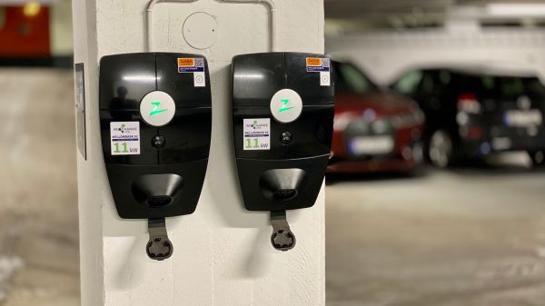
But as this EV charger teardown and reverse engineering shows, it doesn’t necessarily have to be that way. The charger is a Zaptec Pro station that can do up to 22 kW, and the analysis was done by [Harrison Sand] and [Andreas Claesson]. These are just the kinds of chargers that will likely be widely installed over the next decade, and there’s surprisingly little to them. [Harrison] and [Andreas] found a pair of PCBs, one for the power electronics and one for the control circuits. The latter supports a number of connectivity options, like 4G, WiFi, and Bluetooth, plus some RFID and powerline communications. There are two microcontrollers, a PIC and an ARM Cortex-A7.

Despite the ARM chip, the board seemed to lack an obvious JTAG port, and while some unpopulated pads did end up having a UART line, there was no shell access possible. An on-board micro SD card slot seemed an obvious target for attack, and some of the Linux images they tried yielded at least a partial boot-up, but without knowing the specific hardware configuration on the board, that’s just shooting in the dark. That’s when the NAND flash chip was popped off the board to dump the firmware, which allowed them to extract the devicetree and build a custom bootloader to finally own root.

The article has a lot of fascinating details on the exploit and what they discovered after getting in, like the fact that even if you had the factory-set Bluetooth PIN, you wouldn’t be able to get free charging. So overall, a pretty good security setup, even if they were able to get in by dumping the firmware. This all reminds us a little of the smart meter reverse engineering our friend [Hash] has been doing, in terms of both methodology and results.

Thanks to [Thinkerer] for the tip.

When [Elon] Says No, Just Reverse Engineer The Starlink Signal

We all know that it’s sometimes better to beg forgiveness than ask permission to do something, and we’ll venture a guess that more than a few of us have taken that advice to heart on occasion. But [Todd Humphreys] got the order of operations a bit mixed up with his attempt to leverage the Starlink network as a backup to the Global Positioning System, and ended up doing some interesting reverse engineering work as a result.

The story goes that [Todd] and his team at the University of Texas Austin’s Radionavigation Lab, on behalf of their sponsors in the US Army, approached Starlink about cooperating on a project to make their low-Earth orbit constellation provide position, navigation, and timing capabilities. Although initially interested in the project, Starlink honcho [Elon Musk] put the brakes on things, leaving [Todd]’s team high and dry. Not to be dissuaded, they bought a Starlink user terminal, built what amounts to a small radiotelescope — although we’ve seen something similar done with just an RTL-SDR — and proceeded to reverse-engineer the structure of Starlink’s Ku-band downlink signal. The paper (PDF link) on their findings is densely packed with details, such as the fact that Starlink uses an orthogonal frequency-division multiplexing (OFDM) scheme.

It’s important to note that their goal was not to break encryption or sniff in on user data; rather, they wanted access to the synchronization and timing signals embedded in the Starlink data structures. By using this data along with the publically available ephemera for each satellite, it’s possible to quickly calculate the exact distance to multiple satellites and determine the receiver’s location to within 30 meters. It’s not as good as some GPS-Starlink hacks we’ve seen, but it’s still pretty good in a pinch. Besides, the reverse engineering work here is well worth a read.

Thanks to [Adrian] for the tip!

An LCD mounted inside a Roland synthesizer

Reverse-Engineering A Display Protocol To Repair A Roland Synthesizer

Repairing electronic devices isn’t as hard as it used to be. Thanks to the internet, it’s easy to find datasheets and application notes for any standard component inside your gadget, and once you’ve found the faulty one, you simply buy a replacement from one of a million web shops — assuming you don’t end up with a fake, of course. When it comes to non-standard components, however, things get more difficult, as [dpeddi] found out when a friend asked him for help in repairing a Roland Juno-G synthesizer with a broken display.

The main issue here was the fact that the display in question was a custom design, with no replacement or documentation available. The only thing [dpeddi] could figure out from the service manual was the basic pinout, which showed a parallel interface with two lines labelled “chip select” — an indication that the display contained two separate controllers. But the exact protocol and data format was not documented, so [dpeddi] brought out his logic analyzer to try and decode the signals generated by the synthesizer.

After a bit of trial and error, he was able to figure out the protocol: it looked like the display contained two KS0713-type LCD controllers, each controlling one half of the screen. Finding a compatible replacement was still proving difficult, so [dpeddi] decided instead to decode the original signals using a microcontroller and show the picture on a modern LCD driven by SPI. After some intial experiments with an ESP32, it turned out that the task of reading two reasonably fast parallel buses and driving an even faster serial one was a bit too much for the ESP, so [dpeddi] upgraded to a Raspberry Pi Pico. This worked a treat, and thanks to a 3D-printed mounting bracket, the new display also fit snugly inside the Roland’s case.

The Pico’s code is available on [dpeddi]’s GitHub page, so if you’ve also got a dodgy display in your Juno-G you can simply download it and use it to plug in a brand-new display. However, the method of reverse-engineering an existing display protocol and translating it to that of a new one is pretty universal and should come in handy when working with any type of electronic device: say, a vintage calculator or multimeter, or even another synthesizer.

An 8-bit ISA card being plugged into a motherboard

Reverse-Engineering An ISA Card To Revive An Ancient CD-ROM Drive

Being an early adopter is great if you enjoy showing off new gadgets to your friends. But any new technology also brings the risk of ending up at the wrong side of a format war: just ask anyone who committed to HD-DVD fifteen years ago. If, on the other hand, you were among the few who invested in CD-ROM when it was first released in the mid-1980s, you definitely made the right choice when it came to storage media. However, it was a bit of a different story for the interface that hooks up the CD drive to your computer, as [Tech Tangents] found out when he managed to get his hands on a first-generation CM100 drive. (Video, embedded below.)

That wonderful piece of 1985 technology is not much smaller than the IBM PC it was designed to connect to, and it originally came with its own CM153 ISA interface card. But while most eBay sellers recognized the historic value of a pioneering CD-ROM drive, the accompanying PC was typically a dime-a-dozen model and was thrown out with the rare interface card still inside. Even after searching high and low for over a year, the only information [Tech Tangents] could find about the card was a nine year old YouTube video that showed what the thing looked like.

A 3D rendered image of an 8-bit ISA cardLuckily, the maker of that video was willing to take high-resolution pictures of the card, which allowed [Tech Tangents] to figure out how it worked. As it turned out, the card was entirely made from standard 7400 series logic chips as well as an 8251 USART, which meant that it should be possible to design a replacement simply by following all the traces on the board. [Tech Tangents] set to work, and after a few weeks of reverse-engineering he had a complete schematic and layout ready in KiCAD.

After the PCBs were manufactured and populated with components, it was time to test the new card with the old drive. This wasn’t a simple process either: as anyone who’s tried to get obscure hardware to work in MS-DOS will tell you, it involves countless hours of trying different driver versions and setting poorly documented switches in CONFIG.SYS. Eventually however, the driver loaded correctly and the ancient CD-ROM drive duly transferred the files stored on a Wolfenstein 3D disk.

If you’re lucky enough to own a CM100 or a similar drive from that era, you’ll be happy to know that all design files for the CM153 clone are available on GitHub. This isn’t the first time someone has had to re-create an interface board from pictures alone: we’ve seen a similar project involving a SCSI card for a synthesizer. Thanks for the tip, [hackbyte]!

Continue reading “Reverse-Engineering An ISA Card To Revive An Ancient CD-ROM Drive”

Reverse Engineering Hack Chat With Matthew Alt

Join us on Wednesday, September 28 at noon Pacific for the Reverse Engineering Hack Chat with Matthew Alt!

Our world is full of mysteries, from the nature of time to how exactly magnets work. There are some things that we just have to accept that no matter how hard we look, we’ll never get a complete answer, especially in the natural world. The constructed world is another thing, though. It doesn’t seem fair that only a relatively few people have the inside scoop on the workings of everyday things, like network routers, game consoles, and even the vehicles we drive. Of course, the companies that make these things have a right to profit from their intellectual property, but we as consumers also have a right to be curious about how these things work and to understand what the software running on these devices is doing on our behalf.

join-hack-chatLuckily, what can be engineered can be reverse engineered, if you have the right tools and the skills to use them. It can be a challenge, but it’s one Matthew Alt has taken on plenty of times. We’ve seen him deep-dive into JTAG, look at serial wire debugging, and recently even try some glitching attacks. In fact, he even taught a HackadayU course on reverse engineering with Ghidra. And now he’ll drop by the Hack Chat to talk all about reverse engineering. Join us with your questions, your exploits, and your ideas on how to go where no hacker has gone before.

Our Hack Chats are live community events in the Hackaday.io Hack Chat group messaging. This week we’ll be sitting down on Wednesday, September 28 at 12:00 PM Pacific time. If time zones have you tied up, we have a handy time zone converter.

Arduino Nano Powers Reverse Polish Notation Calculator

There’s something about Reverse Polish Notation (RPN) and the calculators that use it. It calls to mind a time when a calculator was a serious tool, and not just a throwaway toy. Created in the legacy of such calculators by HP and Texas Instruments, [Simon Boak] shows off his SB116, sporting an Arduino Nano under the hood. It’s a fully custom design, with a hand-built metal case, a custom PCB for the keyboard, and a tiny OLED display for maximum retro green goodness.

The impetus for this build was to replace a particular calculator, a well-used TI Programmer, that’s useful for working with 6502 assembly. The SB116 supports binary, octal, decimal, and hex; and boasts some downright useful functions — AND, NOT, OR, XOR, and bitshifts. The source code is available, but you’re on your own for the case and keyboard. And for maximized retro faux-nostalgia, [Simon] designed a box that would have looked right at home on an 80s store shelf.

Stick around for more retro-modern takes on calculators, or tales of repairing a genuine vintage model.

Reverse-Engineering A Smoker

In certain parts of the world, cooking meat in a regionally-specific way is a critical part of the local culture. From barbeque in the American south to boerewors and braaivleis in South Africa to Montréal smoked meat in French Canada, almost every location has its cookout specialty. So much so that various manufacturers of the tools used for these foods include all kinds of gadgets to monitor the sometimes days-long process of cooking various cuts of meat. [megamarco833]’s smoker, though, includes some tools of his own design.

The smoker is made by a company called Pitboss and includes a rotary switch and control board for maintaining a precise temperature in the smoker. The switch works by changing the voltage value sent to a small microcontroller. By interfacing an ESP32 to this switch, [megamarco833] can remotely change the smoke level and temperature of the smoker. On the software side, it uses a combination of Node-RED and Domoticz to handle the automation and control.

For a cookout that can last hours (if not days) a remotely accessible smoker like this is an invaluable tool if you want to do something other than manually monitor the temperature of your meat for that much time. And, if your barbeque grill or smoker of choice doesn’t already have an embedded control board of some type, we’ve seen analog cooking tools adapted to much the same purpose as this one.

Thanks to [Peter] who sent in the tip and also helped [megamarco833] with the reverse-engineering of the control board!