Fusing Cheap EBay Find Into A Digital Rangefinder

One of the earliest commercially-successful camera technologies was the rangefinder — a rather mechanically-complex system that allows a photographer to focus by triangulating a subject, often in a dedicated focusing window, and and frame the shot with another window, all without ever actually looking through the lens. Rangefinder photographers will give you any number of reasons why their camera is just better than the others — it’s faster to use, the focusing is more accurate, the camera is lighter — but in today’s era of lightweight mirrorless digitals, all of these arguments sound like vinyl aficionados saying “The sound is just more round, man. Digital recordings are all square.” (This is being written by somebody who shoots with a rangefinder and listens to vinyl).

While there are loads of analog rangefinders floating around eBay, the trouble nowadays is that digital rangefinders are rare, and all but impossible to find for a reasonable price. Rather than complaining on Reddit after getting fed up with the lack of affordable options, [Mr.50mm] decided to do something about it, and build his own digital rangefinder for less than $250.

Part of the problem is that, aside from a few exceptions, the only digital rangefinders have been manufactured by Leica, a German company often touted as the Holy Grail of photography. Whether you agree with the hype or consider them overrated toys, they’re sure expensive. Even in the used market, you’d be hard-pressed to find an older model for less than $2,000, and the newest models can be upwards of $10,000.

Rather than start from scratch, he fused two low-cost and commonly-available cameras into one with some careful surgery and 3D printing. The digital bits came from a Panasonic GF3, a 12 MP camera that can be had for around $120, and the rangefinder system from an old Soviet camera called the Fed 5, which you can get for less than $50 if you’re lucky. The Fed 5 also conveniently worked with Leica Thread Mount (LTM) lenses, a precursor to the modern bayonet-mount lenses, so [Mr.50mm] lifted the lens mounting hardware from it as well.

Even LTM lenses are relatively cheap, as they’re not compatible with modern Leicas. Anyone who’s dabbled in building or repairing cameras will tell you that there’s loads of precision involved. If the image sensor, or film plane, offset is off by the slightest bit, you’ll never achieve a sharp focus — and that’s just one of many aspects that need to be just right. [Mr.50mm]’s attention to detail really paid off, as the sample images (which you can see in the video below) look fantastic. Continue reading “Fusing Cheap EBay Find Into A Digital Rangefinder”

Most complex blinking light

2025 One Hertz Challenge: 16-Bit Tower Blinks At One Hertz

We’ve seen our share of blinking light projects around here; most are fairly straightforward small projects, but this entry to the 2025 One Hertz Challenge is the polar opposite of that approach. [Peter] sent in this awesome tower of 16bit relay CPU power blinking a light every second.

There’s a lot to take in on this project, so be sure to go look at the ongoing logs of the underlying 16-bit relay CPU project where [Peter] has been showing his progress in creating this clicking and clacking masterpiece. The relay CPU consists of a stack of 5 main levels: the top board is the main control board, the next level down figures out the address calculations for commands, under that is the arithmetic logic unit level, under the ALU is the output register where you’ll see a 220 V lamp blinking at 1 Hz, and finally at the base are a couple of microcontrollers used for a clock signal and memory. [Peter] included oscilloscope readings showing how even with the hundreds of moving parts going on, the light is blinking within 1% of its 1 Hz goal.

It’s worth noting that while [Peter] has the relay CPU blinking a light in this setup, the CPU has 19 commands to program it, enabling much more complex tasks. Thanks for the amazing-sounding entry from [Peter] for our One Hertz Challenge. Be sure to check out some of the other relay computers we’ve featured over the years for more clicking goodness.

Continue reading “2025 One Hertz Challenge: 16-Bit Tower Blinks At One Hertz”

Diffuse glow of red, green, and blue LEDs embedded in silicone

Embedded LEDs For Soft Robots Made From Silicone

Over on their YouTube channel [Science Buddies] shows us how to embed LEDs in soft robots. Soft robots can be made entirely or partially from silicone. In the video you see an example of a claw-like gripper made entirely from silicone. You can also use silicone to make “skin”. The skin can stretch, and the degree of stretch can be measured by means of an embedded sensor made from stretchy conductive fabric.

As silicone is translucent if you embed LEDs within it when illuminated they will emit diffuse light. Stranded wire is best for flexibility and the video demonstrates how to loop the wires back and forth into a spring-like shape for expansion and contraction along the axis which will stretch. Or you can wire in the LEDs without bending the wires if you run them along an axis which won’t stretch.

The video shows how to make silicone skin by layering two-part mixture into a mold. A base layer of silicone is followed by a strip of conductive fabric and the LED with its wires. Then another layer of silicone is applied to completely cover and seal the fabric and LED in place. Tape is used to hold the fabric and LED in place while the final layer of silicone is applied.

When the LEDs are embedded in silicone there will be reduced airflow to facilitate cooling so be sure to use a large series resistor to limit the current through the LED as much as possible to prevent overheating. A 1K series resistor would be a good value to try first. If you need the LED to be brighter you will need to decrease the resistance, but make sure you’re not generating too much heat when you do so.

If you’re interested in stretchy circuits you might also like to read about flexible circuits built on polyimide film.

Continue reading “Embedded LEDs For Soft Robots Made From Silicone”

The Death Of Industrial Design And The Era Of Dull Electronics

It’s often said that what’s inside matters more than one’s looks, but it’s hard to argue that a product’s looks and its physical user experience are what makes it instantly recognizable. When you think of something like a Walkman, an iPod music player, a desktop computer, a car or a TV, the first thing that comes to mind is the way  that it looks along with its user interface. This is the domain of industrial design, where circuit boards, mechanisms, displays and buttons are put into a shell that ultimately defines what users see and experience.

Thus industrial design is perhaps the most important aspect of product development as far as the user is concerned, right along with the feature list. It’s also no secret that marketing departments love to lean into the styling and ergonomics of a product. In light of this it is very disconcerting that the past years industrial design for consumer electronics in particular seems to have wilted and is now practically on the verge of death.

Devices like cellphones and TVs are now mostly flat plastic-and-glass rectangles with no distinguishing features. Laptops and PCs are identified either by being flat, small, having RGB lighting, or a combination of these. At the same time buttons and other physical user interface elements are vanishing along with prominent styling, leaving us in a world of basic geometric shapes and flat, evenly colored surfaces. Exactly how did we get to this point, and what does this mean for our own hardware projects?

Continue reading “The Death Of Industrial Design And The Era Of Dull Electronics”

Annealing In Space: How NASA Saved JunoCam In Orbit Around Jupiter

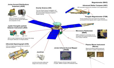
The Juno spacecraft was launched towards Jupiter in August of 2011 as part of the New Frontiers series of spacecraft, on what would originally have been a 7-year mission, including a nearly 5 year cruise to the planet. After a mission extension, it’s currently orbiting Jupiter, allowing for many more years of scientific data to be gathered using its instruments. One of these instruments is the JunoCam (JCM), a visible light camera and telescope. Unfortunately the harsh radiation environment around Jupiter had led many to believe that this camera would fail before long. Now it seems that NASA engineers have successfully tested a fix.

Location of the Juno spacecraft's science instruments. (Credit: NASA)
Location of the Juno spacecraft’s science instruments.

Although the radiation damage to JCM was obvious a few dozen orbits in – and well past its original mission’s 34 orbits – the big question was exactly what was being damaged by the radiation, and whether something could be done to circumvent or fix it. The good news was that the image sensor itself was fine, but one of the voltage regulators in JCM’s power supply was having a bad time. This led the engineers to try annealing the affected part by cranking up one of the JCM’s heaters to a balmy 25°C, well above what it normally is kept at.

This desperate step seemed to work, with massively improved image quality on the following orbits, but soon the images began to degrade again. Before an approach to Jupiter’s moon Io, the engineers thus tried it again but this time cranked the JCM’s heater up to eleven and crossed their fingers. Surprisingly this fixed the issue over the course of a week, until the JCM seems as good as new. Now the engineers are trying their luck with Juno‘s other instruments as well, with it potentially providing a blueprint for extending the life of spacecraft in general.

Thanks to [Mark Stevens] for the tip.

A red, cuboid electrochemical cell is in the center of the picture, with a few wires protruding from the front. Tubes run from each side of the cell to a peristaltic pump and tank on each side. The frame holding the pumps and tanks is white 3D printed plastic.

An Open Source Flow Battery

The flow battery is one of the more interesting ideas for grid energy storage – after all, how many batteries combine electron current with fluid current? If you’re interested in trying your hand at building one of these, the scientists behind the Flow Battery Research Collective just released the design and build instructions for a small zinc-iodide flow battery.

The battery consists of a central electrochemical cell, divided into two separated halves, with a reservoir and peristaltic pump on each side to push electrolyte through the cell. The cell uses brass-backed grafoil (compressed graphite sheets) as the current collectors, graphite felt as porous electrodes, and matte photo paper as the separator membrane between the electrolyte chambers. The cell frame itself and the reservoir tanks are 3D printed out of polypropylene for increased chemical resistance, while the supporting frame for the rest of the cell can be printed from any rigid filament.

The cell uses an open source potentiostat to control charge and discharge cycles, and an Arduino to control the peristaltic pumps. The electrolyte itself uses zinc chloride and potassium iodide as the main ingredients. During charge, zinc deposits on the cathode, while iodine and polyhalogen ions form in the anode compartment. During discharge, zinc redissolves in what is now the anode compartment, while the iodine and polyhalogen ions are reduced back to iodides and chlorides. Considering the stains that iodide ions can leave, the researchers do advise testing the cell for leaks with distilled water before filling it with electrolyte.

If you decide to try one of these builds, there’s a forum available to document your progress or ask for advice. This may have the clearest instructions, but it isn’t the only homemade flow cell out there. It’s also possible to make these with very high energy densities.

Nylon-Like TPU Filament: Testing CC3D’s 72D TPU

Another entry in the world of interesting FDM filaments comes courtesy of CC3D with their 72D TPU filament, with [Dr. Igor Gaspar] putting it to the test in his recent video. The use of the Shore hardness D scale rather than the typical A scale is a strong indication that something is different about this TPU. The manufacturer claims ‘nylon-like’ performance, which should give this TPU filament much more hardness and resistance to abrasion. The questions are whether this filament lives up to these promises, and whether it is at all fun to print with.

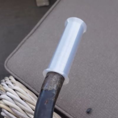
The CC3D 72D TPU filament used to print a bicycle's handlebar. (Credit: My Tech Fun, YouTube)
The CC3D 72D TPU filament used to print a bicycle’s handlebar grips. (Credit: My Tech Fun, YouTube)

TPU is of course highly hydrophilic, so keeping the filament away from moisture is essential. Printing temperature is listed on the spool as 225 – 245°C, and the filament is very bendable but not stretchable. For the testing a Bambu Lab X-1 Carbon was used, with the filament directly loaded from the filament dryer. After an overnight print session resulted in spaghetti due to warping, it was found that generic TPU settings  at 240ºC with some more nylon-specific tweaks seemed to give the best results, with other FDM printers also working well that way.

The comparison was against Bambu Lab’s 68D TPU for AMS. Most noticeable is that the 72D TPU easily suffers permanent deformation, while being much more wear resistant than e.g. PLA. That said, it does indeed seem to perform more like polyamide filaments, making it perhaps an interesting alternative there. Although there’s some confusion about whether this TPU filament has polyamide added to it, it seems to be pure TPU, just like the Bambu Lab 68D filament.

Continue reading “Nylon-Like TPU Filament: Testing CC3D’s 72D TPU”