RAM Upgrade For WRT300N Router

[Heli] had a WRT300N wireless router sitting around collecting dust. He decided to squeeze at bit more entertainment value out of it by seeing if he could pull off a RAM upgrade. He managed to double the router’s RAM and posted a walk through (translated) to help you do the same.

Swapping out surface mount RAM chips isn’t the easiest thing in the world and you must wondering what prompted this. It seems he wanted to run the LuCI package on the router but it was slow (or even incapable) of booting with the stock hardware’s 16 Mb. He first sourced some pin-compatible replacement chips from an old Pentium III computer. While his soldering iron was hot, he also wired up a JTAG header, which connects via the red wires just visible to the left. When he first fired up the unit he was happy that it was able to boot, but it still only detected 16 Mb.

It turns out you’re going to need to roll your own kernel to get it to take advantage of the upgrade. Source code for OpenWRT is easy to find and there’s plenty of guides for compiling it. If you try this, make sure to read [Heli’s] post carefully as he’s got some important configuration information that will help you to avoid bricking your router.

Animatronics In A Box

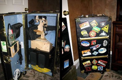
[Knife141] built an impressive animatronic head. He uses it mostly for volunteer activities, like getting school children excited about technology. He built a carrying trunk that fits the puppet just right, making it easy to store and to transport.

He started by making the parts for the head out of cardboard to make sure they would fit together and operate properly. These were then used as templates to cut the pieces out of half-inch plywood. A series of servos, connected either directly or with linking rods, move the mouth, eyes, eyelids, eyebrows and neck via a servo controller board.

Sound is played by a single-board computer called a RAPU via a pair of computer speakers. This board is also what sends commands to the servo controller. When [Knife141] wants to create a new act for the animatronics, he starts by writing the dialog and having a text-to-speech program turn it into an MP3. He then goes through the tedious process of choreographing the puppet to the dialog, a process that generally takes him an hour for each minute of run-time. It’s worth it though, see for yourself by watching one of his acts in the video after the break.

Looking for something a little bit more your speed? Check out this animatronic head which you can build in no time.

Continue reading “Animatronics In A Box”

Robotic Farming Means More Corn For Everyone

You know we’re all going to starve, right? If the world’s population keeps growing exponentially and food production grows linearly, we’re eventually going to find out what Soylent Green is made of. This is where [David Dorhout]’s Prospero robot farmer comes in. [David] has come up with the idea of using small autonomous robots to plant, tend and harvest fields. Right now, he’s working on stage 1: planting seeds.

A swarm of six-legged Prospero robots are dispatched to a field. There, each member of the swarm plants seeds one at a time. The robots keep in contact with each other over a wireless connection to ensure the optimal planting pattern for an entire field.

The Prospero prototype is based on the Parallax Propeller with a Ping ultrasonic sensor used to avoid obstacles. Each hexapod is equipped with a bunch of seeds, a small auger, and a supply of fertilizer for the future corn plant. The next step in the plan is to build a ‘tending’ robot that will monitor and apply nutrients if needed. Check out the Prospero video after the break.

Continue reading “Robotic Farming Means More Corn For Everyone”

Halloween Hacks: Diorama-rama

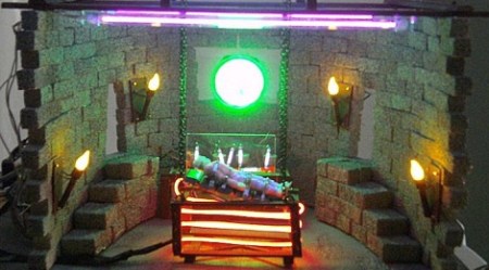
The folks down at LVL1, the Louisville hackerspace, are throwing a Halloween party. To showcase his building skills, LVL1 member [JAC_101] put together a Halloween diorama featuring the inner workings of Doctor Frankenstein’s laboratory.

There’s a bunch of really neat pieces that make this build great. First up is the LVL1 plasma sign. This sign is four circuits pumping a high voltage charge through Xenon flash tubes. Instead of a bright flash, a very Halloweeny Xenon plasma shoots though the tubes. The sign is constructed from four disposable camera flash circuits.

A few flickering-LED torches light Dr. Franenstein’s lair while the monster is a McDonalds happy meal toy wrapped in surgical tape and painted with UV reactive paint.

In the interests of repurposing existing materials, a plasma disc belt buckle was taken from [Seven of Nine]’s regeneration chamber LVL1’s rave supply cabinet and provides a suitable ‘mad scientist’ aesthetic. A bit of EL wire was thrown in for good measure along with some black lights to activate the UV paint.

While Frankenstein’s lab is missing a hilariously oversize knife switch on the wall, [JAC_101] still pulled off a great build.

Detecting DTMF Tones From Scratch

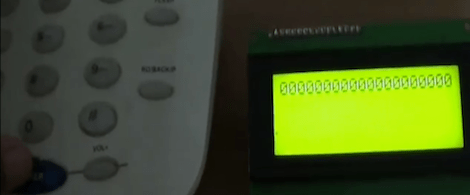
If you’ve ever wondered about the best way to detect dial and DTMF tones from a phone line, [Debraj] is your man.

[Debraj] built a DTMF detector using the Goertzel algorithm. Normally, when we think about detecting tones, we pull FFT out of our bag of tricks. The Goertzel algorithm isn’t as computationally complex as FFT and can be implemented on even the smallest microcontrollers.

For the build, the first thing to solder is a nice audio transformer and some protection diodes. The ring tone from a phone line goes from +35 V to -35 V – a bit more than a microcontroller could handle. A PIC18F4520 dev board was used as the brain of the system with all the code is available on [Debraj]’s site.

Although implementations of the Goertzel algorithm are a little uncommon, [Debraj] has seen a few interesting projects using this technique. [Debraj]’s build could easily be modified into a guitar tuner with a few changes in the code, for example.

This project was built as the command and control for a home automation system and from the video after the break, we can’t wait for [Debraj] to get annoyed at the phrase, “To turn on the kitchen lights, please press 1…”

Continue reading “Detecting DTMF Tones From Scratch”

Rear Window LED Display Gives Other Drivers A Piece Of Your Mind

rear_window_led_matrix

[Gagandeep] was sick and tired of discourteous drivers on the highway, so he decided that he would put together a display to let them know what he thought of their poor driving skills. He planned on putting the display up in the rear window of his car, so he had to ensure that it did not obstruct his view while driving.

He decided that an LED matrix would be the best way for displaying images and text while on the go, so he got busy constructing a 40×16 mesh grid for his rear window. Using a wooden template to get the spacing and positioning just right, he spent several days soldering the 600+ LEDs to one another. He used 74HC595 shift registers to manage the LEDs in groups of 5 columns, while an ATmega AT89C51 was tasked with generating the text and images to be displayed. All of the ICs were deadbugged in place, helping achieve [Gagandeep’s] desire of keeping his view unobstructed.

While we’re not well-versed on the legality of such a display, it looks great when animated. There are plenty of pictures of the grid in various stages of construction as well as videos of it in action in his Picasa album, so be sure to check them out. If you are looking for code or Eagle files, you can find those here.

Analog Test Interface For Your Computer

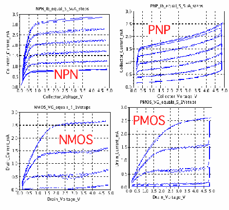
Wanting to test the response curves on some analog parts, [Don Sauer] devised a way of using simple tools to graph analog tests on a computer. Here you can see the results of testing NPN, PNP, NMOS and PMOS transistors, but modifying the input circuitry would let you test just about anything you want.

[Don] is using an Arduino as the hardware interface. He needed some additional parts, like an op-amp and some passives. Instead of building this on a breadboard, he printed the circuit out on a piece of cardboard, hot glued the components in place, then wired them up. This will let him reuse the interface in the future, but is quicker than designing and etching a PCB.

He uses a Processing sketch to capture the test data streaming in from the Arduino. Once recorded, he uses SciLab to create the graphs. He also covers a method of sifting through the data using Octave, another open source program that feels somewhat like MATLAB.