Geiger Counter A/D Conversion For Radiation Level Crowdsourcing

arduino_geiger_counter

[Akiba] and the crew at Tokyo Hakerspace are still hard at work trying to help out their fellow countrymen after the recent earthquake, tsunami, and ongoing nuclear crisis in Japan. You may remember the group as they are behind the Kimono Lantern project we featured last week. This time around, their efforts are focused on getting usable information out to those who need it.

With all of the talk about nuclear fallout, they wanted to see what sort of measurements they could get in Tokyo, however they could not locate a Geiger counter anywhere nearby. Luckily, they were eventually able to source two old counters from the Reuseum in Idaho. One is being lent out to individuals in order to check if their home’s radiation levels are safe, but it was decided that the other would reside outdoors in order to collect radiation readings from the air.

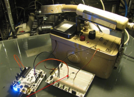
[Akiba] wanted to put the results from the external Geiger counter up on Pachube, however these old units are all analog. He figured that a quick and dirty way to do analog to digital conversion would be to monitor the chirps coming off the counter’s speaker. This was done by wiring up an Arduino to the speaker leads, and keeping track of each time the speaker was activated. This resulted in an accurate digital radiation reading, matching that of the counter’s analog display. The Arduinio wirelessly sends the information to another Arduino stationed inside his apartment, which then uploads the data to Pachube.

A walkthrough of his conversion as well as the source code for both the Arduino counter and the Pachube uploader are available on his site, in case anyone else in the Tokyo area has a Geiger counter handy and wishes to do the same.
Fusion Reactor Wins Science Fairs

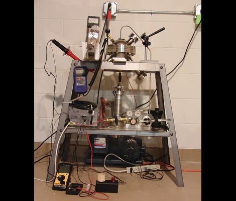
[Will Jack] built a heavy water fusion reactor and then won district and regional science fair projects with it. Someone give this man a job!

We looked in on his fusion reactor about a year ago. At the time he had managed to build a magnetic containment field but didn’t have the voltages or the deuterium necessary to achieve fusion. We’ll that’s all changed. Using a boron-10 lined sensor tube he’s managed to detect the rise in neutron counts that would indicate fusion. Remarkable. He’s now working on a refined gas system that will allow him to increase the deuterium purity by cutting down on the leak rate. He mentions a few other hardware improvements such as a new containment unit and an ion source upgrade. Both of these concepts go beyond our knowledge so do make sure to put on your Nuclear Engineering hat while reading through his project update.

DIY Low-power PSU For Home Server Use

diy_pc_psu

[Viktor] decided to replace his old power hungry home server with a model that is much easier on the old electric bill. The new motherboard uses an Intel Atom chip and consumes far less power than its predecessor. He figured there was no reason to use a bulky ATX power supply when all he needed was 12V for the mainboard and a pair of 5V rails for his hard drives, so he decided to build a PSU himself.

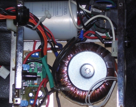
He sourced a 100VA toroid transformer as the basis of the power supply due to its popularity with audio amp builders, adding a standard bridge rectifier and smoothing capacitor before regulating the DC output. A pair of switching regulators were added, one for the 6A, 12V, and a second for the 1.5A, 5V supply. The motherboard only requires about 18W at full tilt, so the PSU should be more than sufficient for his needs.

Schematics and board layouts are available for free on his site, if you are in the market for your own DIY low-power PSU.

Looking for more build to suit electronics?  Check out this DIY amp we featured just the other day.

[Thanks, Chris]

Learn The Geometry To Draw An Analog Clock On A Graphic LCD Screen

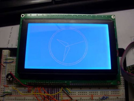
Does the image of the clock above make you shutter with fear because of the math you’d need to use to recreate your own version of the project? We certainly understand that High School geometry is becoming a very distant memory, but it’s really not as hard as you think. [Janw] built this analog clock using a graphic LCD and he’s done a great job of explaining the concepts behind it.

The hardware he’s using is pretty standard for an electronic hobby clock; an ATmega16, graphic LCD, DS1307 real-time clock, and supporting hardware like a potentiometer, resistors, and buttons. The code is written in Bascom, but like we said, [Janw] explains the concepts behind drawing the hands on the clock so you can recreate this with any microcontroller or software language you prefer. We  recommend grabbing a calculator and some blank paper. It took us a few tries to brush the cobwebs out and really grasp what he’s doing with each equation.

Real Life Super Mario Coin Block

mario_coin_block

Instructables user [Bruno] recently constructed a fun little toy that brings a bit of the Mario nostalgia out of the video game universe and into ours. His Super Mario coin block is instantly recognizable from the first Mario game and performs just as you would expect it to. Punching or tapping the bottom of the block releases coins one at a time, complete with sounds straight from the game.

The coin block is constructed from thick cardboard and wrapped in color mock ups of the in-game block. Inside, a spring-loaded tube of coins is placed above a launch arm which is also connected to a spring. A servo actuated arm pulls the launch arm down, dropping a coin from its tube on to the launch arm which is then flung from the top of the box once the servo arm rotates far enough. When this occurs, the built-in MP3 player is triggered to play the “coin sound” from the game. A 555 timer is used to ensure the servo actuated arm rotates once per activation, and a LM386-based amplifier is used to increase the output volume of the MP3 player, both of which operate using rechargeable batteries.

Be sure to check out some of the inner workings as well as the final product in the videos embedded below.

[Thanks, Samjc3]

Continue reading “Real Life Super Mario Coin Block”

Photographing Stuff That’s Not There By Using Stencils

This image was not made in post production, but captured during a long camera exposure. The method uses stencils to add components to a picture. [Alex] built a jig for his camera from a cardboard box. This jig positions a large frame in front of the camera lens where a printed stencil can be inserted. He printed two identical sheets of paper with black covering the area all around the 8-bit joggers. When properly aligned and inserted in the jig, the black parts of the stencil will act to mask the areas where he wants to capture the natural surroundings of the image. Once the camera shutter is triggered, he uses a flash to illuminated the stencil, then removes the the paper image from the jig and ambient light from the dark surrounding is captured during the remainder of the 20-30 second exposure time. The real trick is getting the light levels between the flash and the ambient light to balance and produce a result like the one seen above.

Is anyone else hearing the Punch Out cut-scene music in their heads right about now?