Building A Dead Mouse’s Switch

building_a_better_mousetrap

[Ned] had a mouse problem in a very uncomfortable place.

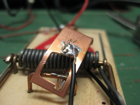
No, not like the back of a Volkswagen, in his ceiling. He wanted to put a mouse trap up there to take care of the critter, but knowing how nasty a tripped trap can be after a few days, he was hesitant. He recalled a project he saw online where a mouse trap was wired like a dead man’s switch and he got to work putting together a trap of his own.

He scavenged some parts from around the house and wired up the mouse trap so that a pair of LEDs were lit so long as the trap had not been sprung on an unsuspecting mouse. Once a mouse is caught in the trap, his circuit is broken, and the LEDs go off, letting [Ned] know it’s time to poke his head back up into the ceiling and clean things up.

While his trap is decidedly low-tech, we always enjoy seeing a cheap and easy solution to annoying, everyday problems.

Easy DIY Stroboscope

stroboscope_output

Looking for something to do in his downtime, [Mista Sparkle] decided that building a simple stroboscope was in order. He already had a set of six LEDs connected to his Arduino from a previous project, so he added a potentiometer to control the rate at which the LEDs flashed, and dug into the IDE.

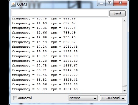
During his build he discovered that using the Arduino millis() function at high speeds provides terrible resolution, while using the micros() function exclusively limits his low end measuring capabilities. He desired a better range of measurement, so his program was broken into main functions: One which measures the LED flashing frequency in milliseconds and another that measures the LED flashing frequency in microseconds. This allowed him to gauge rotational frequencies from 577 to 30,000 RPM.

[Mista Sparkle] admits that he is not yet well-versed in driving displays with the Arduino, so he views his readings over a serial connection on his PC. Hopefully we’ll see an updated version with those features in the near future.

Xteardown

A hot topic in the gadget world right now is the Sony Ericsson XperiaPlay phone, and while that is not our usual cup of tea, when we see the newest toy stripped down to its bits n pieces it piques our interest.

This 8 page teardown of the XperiaPlay (google translated to english) takes you though all the steps needed to dismantle your new joy. Every screw, clip, header and connector, each in order so you can get it back together again.

As the carnage progresses time is taken to point out some of the parts of the phone. From the mundane like I/O jacks, to the more interesting like the Synaptics touch pad driver that are handling the “analog” sticks, the Cypress multi-touch controller for the screen, and of course, the brains.

(thanks Frogz)

Mystery Box Out Of Lego

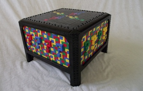
[Todd] recently completed completed his biggest LEGO project, and its pretty wild. The Mystery Box is an 8 compartment LEGO brick puzzle box, covered in a psychedelic pattern of interconnecting question marks.

The question mark pattern was inspired by a few things, the book called “The Curious Incident of the Dog in the Nighttime” contained an illustration that looked sort of like a M.C. Escher painting, which with some looking around brought up tessellation. With the look in mind [Todd] sat down with a paint program, drew out a grid, and started flood filling blocks until the pattern was perfect.

In puzzle box tradition, to gain access to the contents you must remove each compartment in the specific mystery order, and to accomplish this was no easy task. Lego Digital Designer was used to prototype everything on the box and then once happy, [Todd] broke the model down for a parts count.

Nearly 8,000 parts, 35 brick orders, and some long waits, the box was finally completed and its definetly worth a look. If you’re not that extreme, they also make cool electronics enclosures.

MIDI Controller Fit For An Arcade

arcade_midi_controller

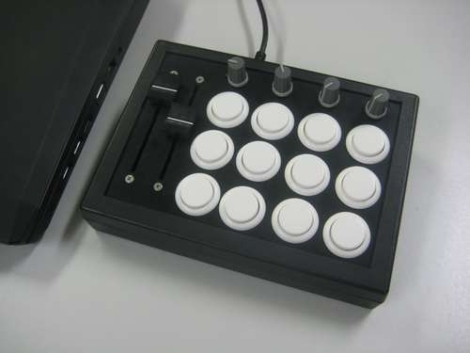
MIDI controllers can be relatively expensive depending on feature sets and requirements, so Instructables user [fraganator] went about building one on his own for just under $100. He originally wanted to replicate a commercially available MIDI controller, which used arcade buttons in lieu of the more common rubberized buttons, since they are large and have a better feel when pressed. Once he drew up plans for his MIDI clone, he realized he wanted more features in his controller than were available in the commercial version, so he started revising.

His final plan included three rows of four arcade buttons as well as four rotary and two sliding potentiometers. All of the components were mounted in a small keyboard enclosure, then wired to an Arduino clone, which manages all of the controller’s functions. The controller is connected to a PC via USB and can perform any number of operations once the buttons are mapped in MIDI-compatible software.

There are no videos of the controller in action just yet, though [fraganator] says one is forthcoming.

The Interstellar Clock

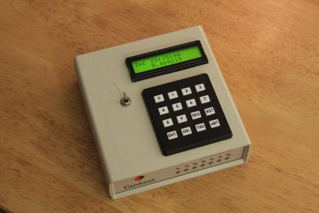
[Alexander Avtanski] has put together a nice clock to meet all your interstellar travel needs. Besides being another PIC based timer, this is a neat little project because it incorporates pretty much every feature you could think of when building a clock for our solar sytem.  For example, it has 16 independent timers and alarms, it can  simultaneously give the time for multiple planets, as well as keep track of other stellar events like the eye of Jupiter or the phases of the moon. To get this project off the ground [Alex] reverse engineered an old dial up modem to serve as an enclosure and power supply and then added in a rechargeable battery so that his  his interstellar clock wasn’t tied to a wall.

[via make]

DIY Racing Sim Shift Box

diy_pc_racing_shiftbox

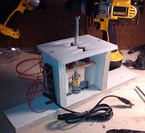
Ask anyone who has ever owned a car with a manual gearbox – in real life and in video games, nothing beats stick shift. Rather than shell out gobs of money to purchase a pre-made shift box, forum member [nikescar] built his own for about $20.

Using some scrap wood and a plastic cutting board, he went to work building a prototype. The “H” shift pattern was designed in CAD and laid over the cutting board, which was hand-cut with a Dremel. Using some tips found online, he constructed a simple shifting mechanism, then wired in a cheap USB game pad found on Ebay. Using safety pins as temporary micro switches, he ran a few laps, and was quite happy with the results. Once the switches arrived, they were fitted to the shift box and it was off to the races.

[nikescar] reports that the shifter works extremely well, allowing him to row through the gears with the greatest of ease, sans any fear of breaking things. Keep reading to get a better look at the shift box internals.

Continue reading “DIY Racing Sim Shift Box”