A DIY split-flap clock in red, black, and white.

Split-Flap Clock Uses Magnets Everywhere

While split-flap alarm clocks once adorned heavy wood nightstands in strong numbers, today the displays are most commonly found in train stations and airports. Hey, at least they’re still around, right? Like many of us, [The Wrench] has always wanted to make one for themselves, but they actually got around to doing it.
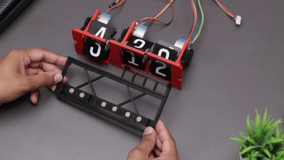
A DIY split-flap clock and its magnetic base.This doesn’t seem like a beginner-friendly project, but [The Wrench] says they were a novice in 3D design and so used Tinkercad to design all the parts. After so many failures, they settled on a design for each unit that uses a spool to attach the flaps, which is turned by a stepper motor.

A small neodymium magnet embedded in the primary gear and a Hall effect sensor determine where the stepper motor is, and in turn, which number is displayed. Everything is handled by an Arduino Nano on a custom PCB.

Aside from the sleek, minimalist look, our favorite part is that [The Wrench] used even more magnets to connect each display segment to the base. You may have noticed that there are only three segments, because the hours are handled by a single display that has flaps for 10, 11, and 12. This makes things simpler and gives the clock an interesting look. Be sure to check out the build video after the break.

Want to build a more complicated clock? Try suspending sand digits in the air with persistence of vision.

Continue reading “Split-Flap Clock Uses Magnets Everywhere”

Ask Hackaday: Do You Calibrate Your Instruments?

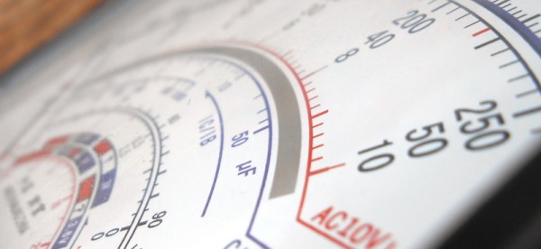
Like many of you, I have a bench full of electronic instruments. The newest is my Rigol oscilloscope, only a few years old, while the oldest is probably my RF signal generator that dates from some time in the early 1950s. Some of those instruments have been with me for decades, and have been crucial in the gestation of countless projects.

If I follow the manufacturer’s recommendations then just like that PAT tester I should have them calibrated frequently. This process involves sending them off to a specialised lab where their readings are compared to a standard and they are adjusted accordingly, and when they return I know I can trust their readings. It’s important if you work in an industry where everything must be verified, for example I’m certain the folks down the road at Airbus use meticulously calibrated instruments when making assemblies for their aircraft, because there is no room for error in a safety critical application at 20000 feet.

But on my bench? Not so much, nobody is likely to face danger if my frequency counter has drifted by a few Hz. Continue reading “Ask Hackaday: Do You Calibrate Your Instruments?”

Displays We Love Hacking: LVDS And EDP

There are times when tiny displays no longer cut it. Whether you want to build a tablet or reuse some laptop displays, you will eventually deal with LVDS and eDP displays. To be more exact, these are displays that want you to use either LVDS or eDP signaling to send a picture.

Of the two, LVDS is the older standard for connecting displays, and eDP is the newer one. In fact, eDP has mostly replaced LVDS for things like laptop and tablet displays. Nevertheless, you will still encounter both of these in the wild, so let’s start with LVDS.

The name “LVDS” actually comes from the LVDS signaling standard (Low-Voltage Differential Signaling), which is a fairly generic data transfer standard over differential pairs, just like RS485. Using LVDS signaling for embedded display purposes is covered by a separate standard called FPD-Link, and when people say “LVDS”, what they’re actually talking about is FPD-Link. In this article, I will also use LVDS while actually talking about FPD-Link. Barely anyone uses FPD-Link except some datasheets, and I’ll use “LVDS” because that’s what people actually use. It’s just that you deserve to know the distinction so that you’re not confused when someone mentions LVDS when talking about, say, industrial machinery.

Both LVDS and eDP run at pretty high frequencies – they’re commonly used for color displays with pretty large resolutions, so speed can no longer be a constraint. eDP, as a successor technology, is a fair bit more capable, but LVDS doesn’t pull punches either – if you want to make a 1024 x 768 color LCD panel work, you will use LVDS, sometimes parallel RGB – at this point, SPI just won’t cut it. There’s a lot of overlap – and that’s because LVDS is basically parallel RGB, but serialized and put onto diffpairs. Let me show you how that happened, and why it’s cool.

Continue reading “Displays We Love Hacking: LVDS And EDP”

The Computers Of Voyager

After more than four decades in space and having traveled a combined 44 billion kilometers, it’s no secret that the Voyager spacecraft are closing in on the end of their extended interstellar mission. Battered and worn, the twin spacecraft are speeding along through the void, far outside the Sun’s influence now, their radioactive fuel decaying, their signals becoming ever fainter as the time needed to cross the chasm of space gets longer by the day.

But still, they soldier on, humanity’s furthest-flung outposts and testaments to the power of good engineering. And no small measure of good luck, too, given the number of nearly mission-ending events which have accumulated in almost half a century of travel. The number of “glitches” and “anomalies” suffered by both Voyagers seems to be on the uptick, too, contributing to the sense that someday, soon perhaps, we’ll hear no more from them.

That day has thankfully not come yet, in no small part due to the computers that the Voyager spacecraft were, in a way, designed around. Voyager was to be a mission unlike any ever undertaken, a Grand Tour of the outer planets that offered a once-in-a-lifetime chance to push science far out into the solar system. Getting the computers right was absolutely essential to delivering on that promise, a task made all the more challenging by the conditions under which they’d be required to operate, the complexity of the spacecraft they’d be running, and the torrent of data streaming through them. Forty-six years later, it’s safe to say that the designers nailed it, and it’s worth taking a look at how they pulled it off.

Continue reading “The Computers Of Voyager”

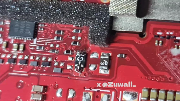
the PTC fuse to blame for the fault described, on the ROG Ally board, with a wire soldered across the fuse

ROG Ally SD Card Slot Fix Shines Light On PTC Fuse Failure Modes

The Asus ROG Ally is a handheld that, to our pleasant surprise, has attracted a decently sized modding community. Recently, we’ve stumbled upon a Reddit post investigating a somewhat common failure mode of this handheld — the microSD card slot going out of order, where an inserted card fails to be recognized, pretty irritating to encounter. Now, it turns out, this is down to a certain model of PTC fuses being failure-prone.

It makes sense to fuse the SD card slot. The cards are dense pieces of technology that are subject to some wear and tear in daily use. As such, it’s not unheard of that a microSD card can short-circuit internally — heating up to the point of melting plastic and giving people severe burns. Given that such a card is typically connected to a beefy 3.3 V rail, any mass-manufactured device designer could want to put a fuse between the 3.3 V rail and the card. However, on some ROG Ally batches, a certain make of the fuse is used, that appears to be likely to develop faults: the fuse’s resistance increasing dramatically during the card’s normal operation, with the SD card being supplied subpar power as a result.

There’s a fair bit of investigating happening in the comment section, with people posting oscilloscope captures, using breakouts to tap the SD card, and figuring out the fuse part numbers for the affected models. As for Reddit’s solution, it’s short-circuiting the fuse with a piece of thin wire — we would probably source a suitable fuse and solder it on top of the faulty one.

This isn’t the first ROG Ally modification we’ve covered so far, and given the activity we’re seeing, it’s unlikely to be our last.

My Space

If I could name one thing which has been the most transformative for our community over the last couple of decades, it would have to be the proliferation of hackerspaces. Ostensibly a place which provides access to tools and machinery, these organisations have become so much more. They bring together like-minded people, and from such a meeting of minds have come a plethora of high quality projects, events, and other good things.

Just What Is A Hackerspace?

A workshop with benches that have small vehickes in various stages of construction on them.
A Hacky Racer takes shape in the MK Makerspace workshop

Hackerspaces loosely come in many forms, from co-working spaces or libraries who have invested in a 3D printer and imagine themselves to be a hackerspace, through to anarchist collectives in abandoned warehouses who support their city’s alternative communities with technology. For me, hackerspaces must be community organisations rather than for-profit ones, so for the purposes of this article I’m not referring to closely-allied commercial spaces such as FabLabs.

So a good hackerspace for me is a group of tech enthusiasts who’ve come together, probably formed a non-profit association, and rented a dilapidated basement or industrial unit somewhere. The tools and machines inside aren’t shiny and new but they mostly work, and round that fridge stocked with Club-Mate you’ll find a community of friends, people who don’t think it’s odd to always want to know how things work. In a good hackerspace you’ll have found your place, and you can be much more than you would have been alone.

I visit plenty of hackerspaces across Europe as I wander the continent on an Interrail pass. I’m a member of three of them at the moment, though my main home in the UK is at Milton Keynes Makerspace. I’ve sat on recycled sofas drinking caffeinated beverages in more cities than I can count, and along the way I’ve seen close-up the many different ways a hackerspace can be run. I’ve seen spaces falling apart at the seams, I’ve seen ones a little too regimented for my taste, and others with too much of an emphasis on radical ideology, but mostly I’ve seen spaces that get it about right and I feel at home in. So perhaps it’s time to sit down and talk about what I think makes a good hackerspace. What is my space?

Continue reading “My Space”

Put More Korry In Your Flight Sim Switches

Never underestimate how far some flight simulator aficionados will go with their builds. No detail is too small, and every aspect of the look and feel has to accurately reflect the real cockpit. As a case in point, check out these very realistic Korry buttons that [Santi Luib III] built for an Airbus A320 simulator.

Now, you might never have heard of a “Korry button” before, but chances are you’ve seen them, at least in photos of commercial or military aircraft cockpits. Korry is a manufacturer of switches and annunciators for the avionics industry, and the name has become shorthand for similar switches. They’ve got a very particular look and feel and are built to extremely high standards, as one hopes that anything going into a plane would be. That makes the real switches very expensive, far more so than even the most dedicated homebrew sim builder would be comfortable with.

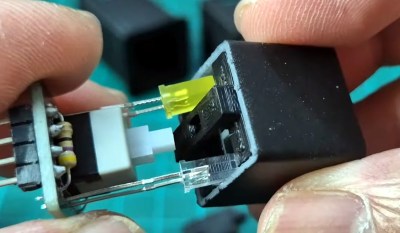
That’s where [Santi] comes in. His replica Korry buttons are built from off-the-shelf parts like LEDs and switches mounted to custom PCBs. The PCB was designed for either momentary or latching switches, and can support multiple LEDs in different colors. The assembled PCBs snap into 3D printed enclosures with dividers to keep light from bleeding through from one legend to the other.

The lenses are laser-cut translucent acrylic painted with urethane paint before the legends are engraved with a laser. The attention to detail on the labels is impressive. [Santi]’s process, which includes multiple coats of sealers, gets them looking just right. Even the LEDs are carefully selected: blue LEDs are too bright and aren’t quite the proper shade, so [Santi] uses white LEDs that are dimmed down with a bigger resistor and a light blue photographic gel to get the tint just right.

These buttons are just beautiful, and seeing a panel full of them with the proper back-lighting must be pretty thrilling. If civil aviation isn’t your thing, check out this A-10 “Warthog” cockpit sim, and the cool switches needed to make it just right.

Continue reading “Put More Korry In Your Flight Sim Switches”