The early 1990s were an interesting time in the PC world, mainly because PCs were entering the zeitgeist for the first time. This was fueled in part by companies like Intel and AMD going head-to-head in the marketplace with massive ad campaigns to build brand recognition; remember “Intel Inside”?
In 1993, Intel was making some headway in that regard. The splashy launch of their new Pentium chip in 1993 was a huge event. Unfortunately an esoteric bug in the floating-point division module came to the public’s attention. [Ken Shirriff]’s excellent account of that kerfuffle goes into great detail about the discovery of the bug. The issue was discovered by [Dr. Thomas R. Nicely] as he searched for prime numbers. It’s a bit of an understatement to say this bug created a mess for Intel. The really interesting stuff is how the so-called FDIV bug, named after the floating-point division instruction affected, was actually executed in silicon.
We won’t presume to explain it better than [Professor Ken] does, but the gist is that floating-point division in the Pentium relied on a lookup table implemented in a programmable logic array on the chip. The bug was caused by five missing table entries, and [Ken] was able to find the corresponding PLA defects on a decapped Pentium. What’s more, his analysis suggests that Intel’s characterization of the bug as a transcription error is a bit misleading; the pattern of the missing entries in the lookup table is more consistent with a mathematical error in the program that generated the table.
The Pentium bug was a big deal at the time, and in some ways a master class on how not to handle a complex technical problem. To be fair, this was the first time something like this had happened on a global scale, so Intel didn’t really have a playbook to go by. [Ken]’s account of the bug and the dustup surrounding it is first-rate, and if you ever wanted to really understand how floating-point math works in silicon, this is one article you won’t want to miss.
There are many retrocomputer emulation projects out there, and given the relative fragility of the original machines as they enter their fifth decade, emulation seems to be the most common way to play 8-bit games. It’s easy enough to load one on your modern computer, but there are plenty of hardware options, too. “The computer we’d have done anything for back in 1983” seems to be a phrase many of them bring to mind, but it’s so appropriate because they keep getting better. Take [Stormbytes1970]’s Pi Pico-powered Sinclair ZX Spectrum mini laptop (Spanish language, Google Translate link), for example. It’s a slightly chunky netbook that’s a ZX Spectrum, and it has a far better keyboard than the original.
On the PCB is the Pico, the power supply circuitry, an SD card, and a speaker. But it’s when the board is flipped over that the interesting stuff starts. In place of the squidgy rubber keyboard of yore, it has a proper keyboard,. We’re not entirely sure which switch it uses, but it appears to be a decent one, nevertheless. The enclosure is a slick 3D-printed sub-netbook for retro gaming on the go. Sadly, it won’t edit Hackaday, so we won’t be slipping one in the pack next time we go on the road, but we like it a lot.
By the end of World War II the world had changed forever, as nuclear weapons were used for the first and – to this date – only time in anger. Although the use of these weapons was barely avoided during the Korean War in the early 1950s, the dawning of the Atomic Age had come in the form of obliterated cities and an increasing number of these weapons being test fired around the world. It was against this background that on December 8, 1953, US President Dwight D. Eisenhower held his ‘Atoms for Peace’ speech, during which he would not only promote the peaceful use of nuclear technologies but also lay the groundwork for what would become the International Atomic Energy Agency (IAEA), as announced in the full speech.
Under the Eisenhower administration the US became one of the world’s nuclear power pioneers, as it competed with the UK and later others in establishing world’s firsts in commercial nuclear power. Dresden Generating Station would become the first purely commercial boiling water reactor (BWR) in 1960 and Yankee-Rowe, the first pressurized water reactor (PWR) in 1961. Following these, the number of new reactors planned and constructed kept increasing year over year, setting the trend for the few decades of the US nuclear power industry.
Today the US operates 94 reactors, which generate nearly 20% of the country’s electricity. Exactly how did the US build so many reactors before 1990, and how does this compare to the recent revival with both new builds and retired plants being put back into service?
The ESP32 is s remarkably powerful microcontroller, where its dual-core processor and relatively high clock speed can do some impressive work. But getting this microcontroller designed for embedded systems to do tasks that would generally be given to a much more powerful PC-type computer takes a little bit more willpower. Inspired by his dog, [Folkert] decided to program an ESP32 to play chess, a famously challenging task for computer scientists in the past. He calls this ESP32 chess system Dog.
One of the other major limitations of this platform for a task like this is memory. The ESP32 [Folkert] is using only has 320 kB of RAM, so things like the transposition table have to fit in even less space than that. With modern desktop computers often having 32 or 64 GB, this is a fairly significant challenge, especially for a memory-intensive task like a chess engine. But with the engine running on the microcontroller it’s ready to play, either in text mode or with something that can use the Universal Chess Interface (UCI). A set of LEDs on the board lets the user know what’s going on while gameplay is taking place.
Twas the week before Christmas when Elliot and Dan sat down to unwrap a pre-holiday bundle of hacks. We kicked things off in a seasonally appropriate way with a PCB Christmas card that harvests power from your microwave or WiFi router, plus has the potential to be a spy tool. We learned how to grow big, beautiful crystals quickly, just in case you need some baubles for the tree or a nice pair of earrings. Speaking of last-minute gifts, perhaps you could build a packable dipole antenna, a very durable PCB motor, or a ridiculously bright Fibonacci simple add-on for your latest conference badge. We also looked into taking a shortcut to homebrew semiconductors via scanning electron microscopes, solved the mystery of early CD caddies, and discussed the sad state of table saw safety and the lamentable loss of fingers, or fractions thereof.
Analog radio broadcasts are pretty simple, right? Tune into a given frequency on the AM or FM bands, and what you hear is what you get. Or at least, that used to be the way, before smart engineers started figuring out all kinds of sneaky ways for extra signals to hop on to mainstream broadcasts.
Subcarrier radio once felt like the secret backchannel of the airwaves. Long before Wi-Fi, streaming, and digital multiplexing, these hidden signals beamed anything from elevator music and stock tickers to specialized content for medical professionals. Tuning into your favorite FM stations, you’d never notice them—unless you had the right hardware and a bit of know-how.
We talk a lot about patent disputes in today’s high-tech world. Whether it’s Wi-Fi, 3D printing, or progress bars, patent disputes can quickly become big money—for lawyers and litigants alike.
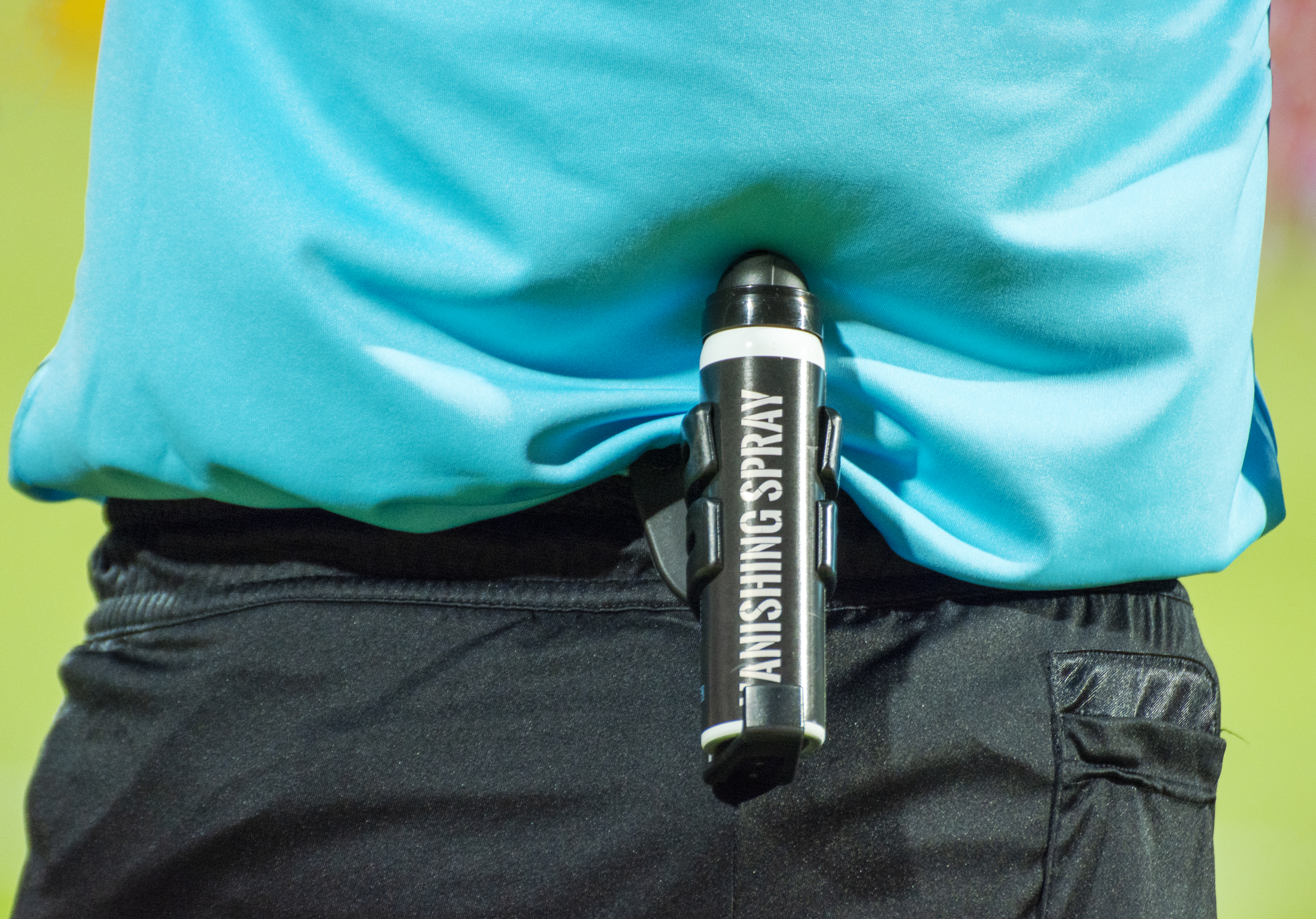
Where we see less of this, typically, is the world of sports. And yet, a recent football innovation has seen plenty of conflict in this very area. This is the controversial story of vanishing spray.
Patently Absurd
Vanishing spray has quickly become a common sight on the belts of professional referees. Credit: Balkan Photos, CC BY-SA 2.0
You might have played football (soccer) as a child, and if that’s the case, you probably don’t remember vanishing spray as a key part of the sport. Indeed, it’s a relatively modern innovation, which came into play in international matches from 2013. The spray allowed referees to mark a line with a sort of disappearing foam, which could then be used to enforce the 10-yard distance between opposing players and the ball during a free kick.
The product is a fairly simple aerosol—the cans contain water, butane, a surfactant, vegetable oil, and some other minor constituents. When the aerosol nozzle is pressed, the liquified butane expands into a gas, creating a foam with the water and surfactant content. This creates an obvious white line that then disappears in just a few minutes.
The spray was created by Brazilian inventor Heine Allemagne in 2000, and was originally given the name Spuni. He filed a patent in 2000, which was then granted in 2002. It was being used in professional games by 2001, and quickly adopted in the mainstream Brazilian professional competition.
The future looked bright for Allemagne and his invention, with the Brazilian meeting with FIFA in 2012 to explore its use at the highest level of international football. In 2013, FIFA adopted the use of the vanishing spray for the Club World Cup. It appeared again in the 2014 World Cup, and many competitions since. By this time, it had been renamed “9.15 Fair Play,” referring to the metric equivalent of the 10-yard (9.15 meter) distance for free kicks.
After its first use by FIFA, the use of vanishing spray quickly spread to other professional competitions, making its first appearance in the Premier League in 2014. Credit: Egghead06, CC BY-SA 4.0
The controversy came later. Allemagne would go on to publicly claim that the global sporting body had refused to pay him the agreed price for his patent. He would go on to tell the press he’d knocked back an initial offer of $500,000, with FIFA later agreeing to pay $40 million for the invention. Only, the organization never actually paid up, and started encouraging the manufacture of copycat products from other manufacturers. In 2017, the matter went to court, with a Brazilian ruling acknowledging Allemagne’s patent. It also ordered FIFA to stop using the spray, or else face the risk of fines. However, as is often the way, FIFA repeatedly attempted to appeal the decision, raising questions about the validity of Allemagne’s patent.
The case has languished in the legal system for years since. In 2020, one court found against Allemagne, stating he hadn’t proven that FIFA had infringed his products or that he had suffered any real damages. By 2022, that had been overturned on appeal to a higher court, which found that FIFA had to pay material damages for their use of vanishing spray, and for the loss of profits suffered by Allemagne. The latest development occurred earlier this year, with the Superior Court of Justice ruling that FIFA must compensate Allemagne for his invention. In May, CNN reported that he expected to receive $40 million as a result of the case, with all five ministers on the Superior Court ruling in his favor.
Ultimately, vanishing spray is yet another case of authorities implementing ever-greater control over the world of football. It’s also another sad case of an inventor having to fight to receive their due compensation for an innovative idea. What seems like an open-and-shut case nevertheless took years to untangle in the courts. It’s a shame, because what should be a simple and tidy addition to the world of football has become a mess of litigation that cost time, money, and a great deal of strife. It was ever thus.