One of the most crucial aspects of FDM 3D printing is ensuring sufficient material is extruded. Determining the right flow rate can be done manually, but some printers these days automatically perform this adjustment, which is very convenient. [Stefan] of CNC Kitchen investigates how to add similar functionality using existing bed-leveling sensors.
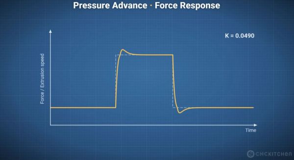
A major complication with extrusion in FDM printers is that the flow rate has to fit the printing speed. However, you can’t just immediately speed up or reduce the flow rate, as the melting filament is flexible and thus acts like a spring, especially as the extruder is exerting significant force on the filament, which adds compression.
The moment you reduce or increase the speed of the nozzle, you can get over- or under-extrusion, but the delayed response by the extruded filament means that you have to adjust for this change in advance. Ergo, the name ‘pressure advance’, also known as the K-value. Obviously, this is a parameter that differs with each material, printer, and other factors, so a direct measurement is always the best.
 In the Bambu Lab X1 FDM printer, a Lidar scanner was used to scan various test patterns to automatically determine the optimal setting. This was later moved to the purge section of the extruder in newer Bambu Lab printers. On other FDM printers, the only available sensor in that area is typically the pressure sensor for bed leveling. Could this sensor make a similar measurement?
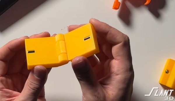
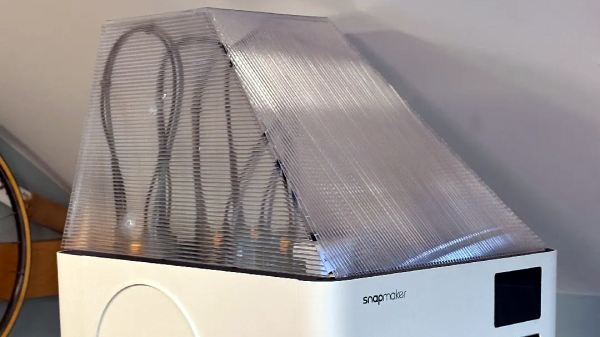
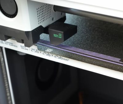
This wasn’t just an idle thought, but was inspired by the Snapmaker U1, which runs open-source Klipper, with tantalizing glimpses of how it does pressure-advance sensing in its extruder. This extruder also only contains a load cell, as do some Prusa printers. These much more open printers thus provided a test bed for some experimentation.
With load cell data available, [Stefan] measured how various extrusion rates affect the load cell, which can then theoretically be correlated with the appropriate K-values for specific transitions. He created a calibration tool for a range of Prusa printers that works with stock firmware, though this is definitely still a work in progress. There are also a couple of similar open-source projects, such as this Auto PA Calibration project by [Mark].
Overall, K-value presets tend to work pretty well, but adding a pressure-advance calibration feature to existing FDM printers is definitely an interesting idea. There’s also the prospect of lateral sensing using this same bed-leveling sensor, which could allow the printer to sense much more than just the bed.
Continue reading “Automated Pressure Advance Using A Bed-Leveling Sensor” →