Computed Axial Lithographic printing gets even closer to the Star Trek replicator fantasy than any other 3D printer we’ve seen: there’s a machine, it glows with a mysterious bluish light, and an object appears. OK, the object is appearing inside a spinning vat of photochemical ooze, not in thin air, but that’s a detail. It’s still very cool tech, and now it’s open source enough to replicate with full documentation and a GitHub repository.
This project is descended from the same Berkeley research that we featured last year, but at that point, they were inviting everyone to join their Discord server, and that was about it. At the time, we put on our old man outfit to yell at clouds and say, “A Discord shouldn’t count as open source!” For once, it looks like those geriatric grumblings were heeded. There is still a corporate-hosted chat server named for a malignant goddess, and you’re still invited, but now there’s also actual, searchable documentation!
If you have a Bambu Labs printer and aren’t keen to send your files to Bambu’s servers with each print job, then check out Bambuddy, an open-source, self-hosted, cloud-free central command that offers a local alternative for managing Bambu Labs printers. It acts as a replacement for the official cloud services, allowing you to slice, print, and monitor with full local control and zero reliance on Bambu Labs’ servers. Continue reading “Bambuddy Says Bye To Bambu Lab Cloud Services”→
Sometimes it’s useful to add extra mass to a 3D print, and [Joe Fedewa] shared a simple and effective technique that uses plaster of Paris. Rather than pause the print and insert hardware or weighted bits inside, he designed the base as hollow. Not in the sense of zero infill, but in the sense of modeling a cavity into the open bottom of the object.
An open cavity in the base is perfect for filling with plaster of Paris.
After the print is complete, he mixes the dry plaster with water until it creates a thick but pourable mixture. Then the object gets turned upside-down and the cavity filled. In about an hour, it will have set up enough to be handled and worked.
Plaster of Paris has a good heft to it, but more importantly it can be made perfectly presentable thanks to being very friendly to post-processing. Any rough spots can be easily sanded and the whole bottom smoothed, so one doesn’t even need to cap it off. Completely cured plaster can be sealed with a clear coat for a more durable finish, if desired.
This basic concept has been used in other ways, such as reinforcing prints with concrete to yield parts solid enough to make tools out of. But using plaster of Paris not just to add mass, but specifically to create a presentable surface that doesn’t need covering up is a neat and highly economical adaptation of the idea.
Other methods of adding mass to a 3D print include inserting metal balls or chunky nuts, bolts, or other hardware, but this method doesn’t require pausing prints to insert things. Nor does it require sealing off or capping the print, messing with goopy epoxies or resins, or spending a lot of money — making it a good one to keep in mind in case it comes in handy someday.
When it comes to robots, few are as iconic as Robby. [Ogrinz Labs] has wanted to build one and even examined a real one up for auction to get high-res photos of it. He also combined his designs with some other open-source designs, and it looks good. He’s released his design as a Creative Commons-licensed set of STL files that you, in theory, could print. There are more details and instructions in the video below.
If you are looking for something quick to print for the weekend, this isn’t it. As you might expect, this is a lot to print. The creator admits, too, that it isn’t totally accurate. It has bigger feet, for example, so his feet can fit inside. There are a few other modifications made for different reasons, but only a hard-core Robby enthusiast would notice any of them.
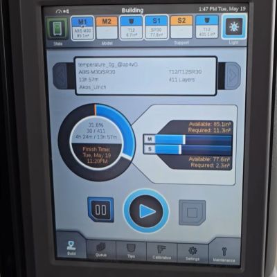
The test parts being printed on the Stratasys Fortus 450mc. (Credit: My Tech Fun, YouTube)
Professional Stratasys FDM printers demand a pretty hefty price premium over your typical hobbyist-level machine, with the gold-plating continuing even with the special filament cartridges that you buy for some of their printers.
This raises the question of in how far this eye-watering price tag is justified, and how much is just you paying for support and the brand name. After acquiring a spool of Stratasys ABS filament via a US viewer, [Dr. Igor Gaspar] set to work to try and answer this question.
The viewer had already liberated the spool of ABS+ P430 filament from its cartridge, making it easy to use that directly with the Bambu Lab FDM printer.
To make it a fair comparison, [Igor] also needed to have a sample printed on a real Stratasys printer, for which he used a local company’s services. An interesting sidenote here is that the US viewer’s company moved away from Stratasys to Bambu Lab printers.
[Igor] was able to see his test parts being printed on the Stratasys printer, as said company is in the same city. This showed him that it took 14 hours to print the parts versus 3.5 hours on the Bambu Lab printer, suggesting that his worries about the right printing parameters for the Stratasys filament were warranted. Sussing those out was thus paramount for a fair comparison and warranted some test prints.
From a sheer aesthetic point of view the Stratasys-printed parts looked much cleaner, and their dimensional accuracy was also significantly better due to the slicer adjusting for this. Between the used Stratasys M30 and Bambu Lab ABS filaments there’s no clear winner, with both trading blows. Amusingly enough, the older Stratasys ABS type in the form of the ABS+ P430 filament performed the best of all when printed on the Bambu Lab printer at its preferred temperature setting.
Moral of the story is thus that – unless you really want to pay for that service contract – to loot old Stratasys ABS spool cartridges and use them in your hobbyist FDM printer. As [Igor] says in the conclusion, the nicer looks is probably due to them printing very thin layers, much finer than the 0.2 mm layers he used. This would also match the much longer print time and is thus something we can replicate on any FDM printer with a temperature-controlled printing environment.
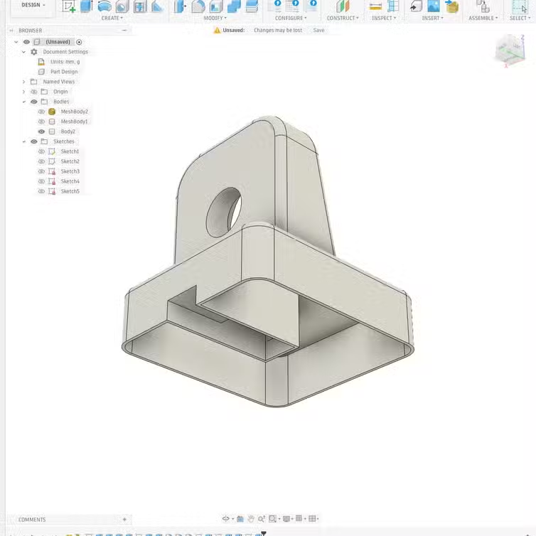
Although no longer so common as during the heyday of the RepRap movement, it’s easier than ever to build your own largely-printed 3D printer, with designs such as Voron’s delivering excellent quality. Nevertheless, there are still niches to be filled by new designs, such as [Alex Yu]’s mostly-printed Encore design.
The Encore uses CoreXY kinematics and linear rails for the X and Y axes. Its has no internal frame; the linear rails are mounted directly to the side panels, which were printed but provided sufficient rigidity. The printer is modular, and all the parts are designed to fit within a 225 mm print bed. The Encore itself uses a 120 mm bed, a Bowden extruder, and a lightweight Bambu-style hotend. The drive motors are NEMA 17 stepper motors, and they use sliding mounts for belt tensioning. The power supply sits behind the rods supporting the Z axis, and the controller board is in the base of the printer.
Building the printer was simple; tuning it, less so. The combination of a Bambu-type hotend with a Bowden extruder created some complications, and the hotend initially received too little cooling. [Alex] solved the cooling issues by using a stronger fan on the hotend, redesigning the ventilation shroud, and adding two inward-blowing fans along the sides of the build volume. After correcting some issues with Z-axis stability, the Encore produced some quite good-looking parts. [Alex] is still improving and documenting some aspects of the printer, but he’s uploaded his progress so far to GitHub.
Unlike resin printers where you generally just pour the fresh resin into the easily accessible vat, FDM printers need to squirrel away at least one spool and its requisite holder somewhere. For bed slingers this generally means a top-mounted spool holder, while for CoreXY enclosed printers they can appear on the sides, top or – inexplicably – on the back. While a side-mounted spool is often convenient, access to the side can still be blocked, in which case you do what [3D Maker Noob] did and over-engineer a fancy top-mounted spool holder.
The problem started after converting a Prusa Mk4S to a Core One using the conversion kit, which changes the position of the spool, forcing him to work around not having access to the right side of the machine where the default position is. After a first version using many of the left-over parts of the original Mk4S to create a fancy box-shaped spool holder, he proceeded to upgrade it as detailed in the video. All project files and instructions are available on Printables.
The result is a box you stack on top of the printer somewhat like a multi-spool box, just flatter and with a flippy lid on the front from which a rail slides out with the magnetically attached spool holder. A spool holder which you naturally can further customize to fit different spools. Even if over-engineered, you can’t deny that it would fit in confined spaces and looks pretty good while doing its job.