Print A Flexible Keypad

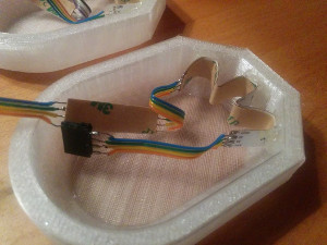
[Micah Elizabeth Scott] needed a custom USB keyboard that wrapped around a post. She couldn’t find exactly what she wanted so she designed and printed it using flexible Nijaflex filament. You can see the design process and the result in the video below.

The electronics rely on a Teensy, which can emulate a USB keyboard easily. The keys themselves use the old resistor divider trick to allow one analog input on the Teensy to read multiple buttons. This was handy, but also minimized the wiring on the flexible PCB.

The board itself used Pyralux that was milled instead of etched. Most of the PCB artwork was done in KiCAD, other than the outline which was done in a more conventional CAD program.

Continue reading “Print A Flexible Keypad”

Visual Development With XOD

Early programmers had to represent code using binary, octal, or hex numbers. This gave way quickly to representing programs as text to be assembled, compiled, or interpreted by the computer. Even today, this remains the most common way to program, but there have been attempts to develop more visual ways to create programs graphically. If you program microcontrollers like the Arduino, you should check out XOD and see how you like visually creating software. The software is open source and currently, can target the Arduino or Raspberry Pi.

Continue reading “Visual Development With XOD”

ATMega328 3D!

Small OLED displays are inexpensive these days–cheap enough that pairing them with an 8-bit micro is economically feasible. But what can you do with a tiny display and not-entirely-powerful processor? If you are [ttsiodras] you can do a real time 3D rendering. You can see the results in the video below. Not bad for an 8-bit, 8 MHz processor.

The code is a “points-only” renderer. The design drives the OLED over the SPI pins and also outputs frame per second information via the serial port.

Continue reading “ATMega328 3D!”

Know The Load With This Simple Microcontroller CPU Meter

How do you tell how much load is on a CPU? On a desktop or laptop, the OS usually has some kind of gadget to display the basics. On a microcontroller, though, you’ll have to roll your own CPU load meter with a few parts, some code, and a voltmeter.

We like [Dave Marples]’s simple approach to quantifying something as complex as CPU load. His technique relies on the fact that most embedded controllers are just looping endlessly waiting for something to do. By strategically placing commands that latch an output on while the CPU is busy and then turn it off again when idle, a PWM signal with a duty cycle proportional to the CPU load is created. A voltage divider then scales the maximum output to 1.0 volt, and a capacitor smooths out the signal so the load is represented by a value between 0 and 1 volt. How you display the load is your own choice; [Dave] just used a voltmeter, but anything from an LED strip to some kind of audio feedback would work too.

Still just looking for a load meter for your desktop? Take your pick: an LED matrixold-time meters, or even Dekatrons.

Mini Hacker Breaks Down How To Build It

I read the other day that the hot career choice for kids these days is: YouTuber. That means every kid — yes, including mine — has two or three attempts at a YouTube show on their account and then they get into the next big thing and forget about it. On the other hand, sometimes you find someone who has a lot of ideas to share, and the dedication to keep sharing them.

[Kevin Zhou], an 11-year-old from Indonesia, has filmed around  70 videos in the past couple of years, with a fantastic variety of nerdy projects ranging from Mindstorms to Arduino to wood shop projects, and even a Blender tutorial. His projects show a lot of complexity, with serious, real-world concepts, and he shares the technical details about the various components in the project, and he walks you through the code as well.

He made a Mindstorms carving machine, pictured above, with a gantry system holding a motor steady while the user carves into a block of floral foam with LEGO bits. He does a lot of home automation projects using an Arduino and relay board, as well as a number of water-pumping robots. He doesn’t stick to one medium or technology. He has a jigsaw and in one video he shows how to build a Thor’s hammer out of wood. He prints out each layer’s design on office paper and glues the paper to a piece of wood, cutting out the cross-sections on his jigsaw. The whole stack is glued together and clamped. [Kevin]’s design featured a hollow space inside to save weight, which he cut by drilling a 1-inch hole in the center with his drill press, then threading the jigsaw blade through the hole to cut out the inside. As an amateur woodcrafter myself, I like seeing him branching out working on small wood projects.

Continue reading “Mini Hacker Breaks Down How To Build It”

Dead Bug Soldered LED Ring Of Awesome

Sometimes the simplest things in life are the most beautiful. [The Tweaker] has soldered an LED circle on the top of an ATmega328P chip, and it looks great.

Using nothing more than some solder, wire, 20 x Pico 0402 (1mm x 0.5mm) blue LEDs and an ATmega328P (7mm x 7mm), [The Tweaker] managed to cram 20 LEDs into a circle on the top of the chip soldered in dead bug style. The chip is running some Arduino code and is operating on the 8 MHz internal crystal oscillator, so that manages to keep the part count low. The soldering is done in a spiral so the LED terminals are hooked up to the right pins, but it seems to add to the aesthetics of the project and looks like it would take a really steady hand. Once you connect a power source it displays chasing lights as well as other light patterns.

There may not be much to this project but it does look great.

Continue reading “Dead Bug Soldered LED Ring Of Awesome”

False Claims On Kickstarter: What’s New?

Kickstarter and its ilk seem like the Wild West when it comes to claims of being “The world’s most (Insert feature here) device!” It does add something special when you can truly say you have the world record for a device though, and [MellBell Electronics] are currently running a Kickstarter claiming the worlds smallest Arduino compatible board called Pico.

We don’t want to knock them too much, they seem like a legit Kickstarter campaign who have at time of writing doubled their goal, but after watching their promo video, checking out their Kickstarter, and around a couple of minutes research, their claim of being the world’s smallest Arduino-compatible board seems to have been debunked. The Pico measures in at an impressive 0.6 in. x 0.6 in. with a total area of 0.36 sq.in. which is nothing to be sniffed at, but the Nanite 85 which we wrote up back in 2014 measures up at around 0.4 in. x  0.7in. with a total area of around 0.28 sq.in.. In this post-fact, fake news world we live in, does it really matter? Are we splitting hairs? Or are the Pico team a little fast and loose with facts and the truth?

There may be smaller Arduino compatible boards out there, and this is just a case study between these two. We think when it comes to making bold claims like “worlds smallest” or something similar perhaps performing a simple Google search just to be sure may be an idea.

Continue reading “False Claims On Kickstarter: What’s New?”