Fail Of The Week is a long-running series here at Hackaday. Over the years we’ve been treated to a succession of entertaining, edifying, and sometimes downright sad cock-ups from many corners of the technological and maker world.
You might think that we Hackaday writers merely document the Fails of others, laughing at others’ misfortunes like that annoying kid at school. But no, we’re just as prone to failure as anyone else, and it is only fair that we eat our own dog food and tell the world about our ignominious disasters when they happen.
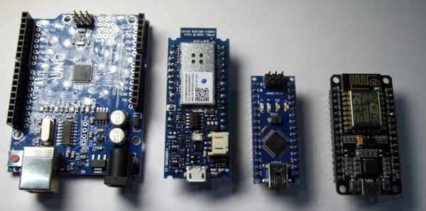
And so we come to my week. I had a test process to automate for my contract customer. A few outputs to drive some relays, a few inputs from buttons and microswitches. Reach for an Arduino Uno and a prototyping shield, divide the 14 digital I/O lines on the right into 7 outputs and 7 inputs. Route 7 to 13 into a ULN2003 to drive my relays, tie 0 to 6 high with a SIL resistor pack so I can trigger them with switches to ground. Job done, and indeed this is substantially the hardware the test rig ended up using.
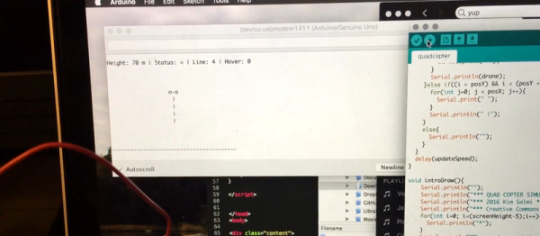
So off to the Arduino IDE to write my sketch. No rocket science involved, a fairly simple set of inputs, outputs, and timers. Upload it to the Arduino, and the LED on pin 13 flashes as expected. Go for a well-deserved lunch as a successful and competent engineer who can whip up a test rig in no time.
Back at the bench refreshed by the finest British pub grub, I started up the PC, plugged the shield into the Arduino, and applied the power. My sketch worked. But wait! There’s a slight bug! Back to the IDE, change a line or two and upload the sketch.
And here comes my fail. The sketch wouldn’t upload, the IDE reported a COM port error. “Damn’ Windows 10 handling of USB serial ports”, I thought, as I’m not a habitual Windows user on my own machines. Then followed something I’ve not done for quite a while; diving into the Windows control panel to chase the problem. Because it had to be a Windows problem, right?
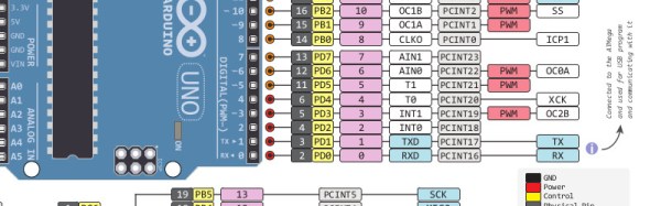
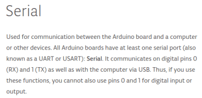 The seasoned Arduinisti among you probably spotted my fail four paragraphs ago. We all know that pins 0 and 1 on an Arduino are shared with the serial port, but who gives it a second thought? I guess I’d always had the good fortune to drive those pins from lines which didn’t enforce a logic state, and had never ended up tying them high. Hold them to a logic 1, and the Arduino can’t do its serial thing so sketches stay firmly in the IDE.
I could have popped the shield off every time I wanted to upload a new sketch, but since in the event I didn’t need all those inputs I just lifted the links tying those pins high and shifted the other inputs up the line. And went home that evening a slightly less competent engineer whose ability to whip up a test rig in no time was a bit tarnished. Ho hum, at least the revised sketch worked and the test rig did its job exactly as it should.
So that’s my Fail Of The Week. What’s yours?
Header image: pighixxx.com, CC-BY-ND via MarkusJenkins
 Fail of the Week is a Hackaday column which celebrates failure as a learning tool. Help keep the fun rolling by writing about your own failures and sending us a link to the story — or sending in links to fail write ups you find in your Internet travels.