Learning becomes interesting when you make it fun, interactive and entertaining. [Arkadi] built ShakeIt – an interactive game for the Mini MakerFaire in Jerusalem to demonstrate to kids and grownups how light colors are mixed. It is a follow up to his earlier project – Smart juggling balls which we featured earlier.
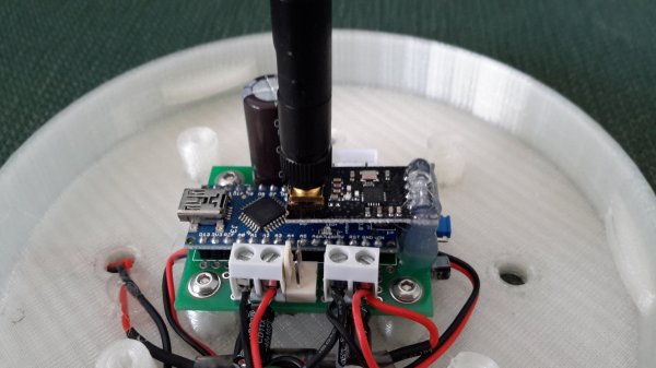
The juggling balls consist of a 6 dof sensor (MPU 6050), a micro controller, transmitter (NRF24L01+), some addressable RGB LED’s and a LiPo battery. An external magnet activates a reed switch inside the balls and triggers them in to action. The ShakeIt light fixture consists of an Arduino Nano clone, NRF24L01+ with SMA Antenna, buck converter, 74 addressable RGB LED’s, and a bluetooth module. The bluetooth module connects to a smartphone app.
[Arkadi] starts out by handing three juggling balls, each with a predefined color (Red, Green, Blue). When the ball is shaken, the light inside the ball becomes stronger. The ShakeIt light fixture is used as a mixer. It communicates with the balls and receives the value of how strong the light inside each of the smart balls is, mixing them up, and generating the mixed color.
The fun starts when the interactive game mode is enabled. Instead of just mixing the light, the Light fixture generates patterns based on how strong the balls are shaken. At first the light fixture shows all three colors filling up the central ball. The three contenders then fight out to get their color to fill up the sphere completely until only one color remains and the winner is declared.
The kids might be learning some color theory here, but it seems the adults are having a “ball” playing the crazy game. If you’d like to build your own shoulder dislocating ShakeIt game, head over to [Arkadi]’s github repository for the ShakeIt and the Juggling Balls. Check the video below to see the adults having fun.