Software Half Duplex UART For AVRs

If you have worked with very low cost microcontroller in the past, such as the ATtiny series from AVR, you’ve probably been stuck without a UART peripheral. The usual answer to this problem is to implement the UART in software. It’s not fast, but it works.

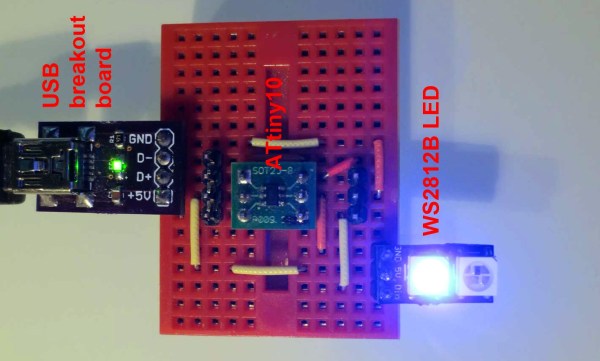
Lets say you’re even more limited on resources, and only have a single pin for UART. [Ralph] created a software library and a small circuit that enables half duplex UART using only one pin. With the above circuit, and a 62 byte Arduino compatible library, you can add UART to the tiniest of ATtinys.

In this circuit, the Tx/Rx pin is on the AVR, and the Tx and Rx pins are another device. The circuit relies on the idle state of UART being a logic high signal. When the Tx pin is idle, the transistor stays on. This allows the Tx/Rx pin to pull Rx low when the AVR sends a 0. When the Tx pin sends a 0, the Tx/Rx pin gets pulled low through the diode.

It’s a clever hack, and could definitely help add communication to your next tiny project.

A Vibrating Timepiece

vibratingWatch

It may not look like much, but the above pictured device is [qquuiinn’s] handy little watch that indicates time through pulsed vibrations. Perhaps we should refrain from labeling it as a “watch,” however, considering it’s [qquuiinn’s] intention to remove the need to actually look at the thing. Vibrations occur in grandfather clock format, with one long vibration for each hour, accompanied by one, two, or three short pulses for the quarter-hour increments.

The design is straightforward, using an ATTiny85 for the brains along with a few analog components. The vibration motor sticks to the protoboard with some glue, joining the microcontroller, a coin cell battery, and a pushbutton on a small protoboard. The button allows for manual time requests; one press responds with the current time (approximated, probably) in vibrations. The build is a work in progress, and [qquuiinn] acknowledges the lack of an RTC (real-time clock) causes some drift in the timepiece’s accuracy. We suspect, however, that you’d address that problem—twice daily—when you replace the battery: it only lasts ten hours.

Trimming The Fat From AVR GCC

avr

[Ralph] has been working on an extraordinarily tiny bootloader for the ATtiny85, and although coding in assembly does have some merits in this regard, writing in C and using AVR Libc is so much more convenient. Through his trials of slimming down pieces of code to the bare minimum, he’s found a few ways to easily trim a few bytes off code compiled with AVR-GCC.

To test his ideas out, [Ralph] first coded up a short program that reads the ATtiny85’s internal temperature sensor. Dissassembling the code, he found the a jump to a function called __ctors_end: before the jump to main. According to the ATtiny85 datasheet, this call sets the IO registers to their initial values. These initial values are 0, so that’s 16 bytes that can be saved. This function also sets the stack pointer to its initial value, so another 16 bytes can be optimized out.

If you’re not using interrupts on an ATtiny, you can get rid of 30 bytes of code by getting rid of the interrupt vector table. In the end, [Ralph] was able to take a 274 byte program and trim it down to 190 bytes. Compared to the 8k of Flash on the ‘tiny85, it’s a small amount saved, but if you’re banging your head against the limitations of this micro’s storage, this might be a good place to start.

Now if you want to hear some stories about optimizing code you’ve got to check out the Once Upon Atari documentary. They spent months hand optimizing code to make it fit on the cartridges.

Cloning The Trinket For A USB Volume Knob

A while back, [Rupert] wrote a blog post on using V-USB with the very small, 8-pin ATtiny85. Since then, the space of dev boards for 8-pin micros with USB has exploded, the most recent being Adafruit’s Trinket. [Rupert] liked what he saw with the Trinket bootloader and decided to clone the circuit into a useful package. Thus was born an awesome looking USB volume knob complete with a heavy aluminum knob, rotary encoder, and RGB LED strip.

[Rupert] got his V-USB/ATtiny85/rotary encoder circuit working, and at the expense of a ‘mute’ control, also added an awesome looking RGB LED ring powered by Adafruit’s Neopixels. The PCB [Rupert] fabbed is pretty well suited for being manufactured one-sided. If you’ve ever wanted an awesome volume knob for your computer, all the files are available form [Rupert]’s blog.

Just as an aside, [Rupert] has been working on getting the Trinket bootloader working on the ATtiny84, a very similar microcontroller to the ’85, but with eight analog pins. It’s a neat device that I’ve made a small V-USB breakout board for, but like [Rupert], I’m stuck on porting the bootloader. If anyone has the Trinket/Gemma firmware running on an ATtiny84, send that in. We’ll put it up.

Pseudo-Random Flickering Jack-O-Lantern LED Using ATtiny13

Pseudo_Random_Flicker_ATtiny13

It’s time to get those jack-o-lanterns twinkling for Halloween. If you don’t want to use candles or buy a jack-o-lantern light this Halloween you can do like [Johannes Bauer] and code your own pseudo-random flickering super bright LED. His wife wanted their pumpkin to be illuminated this year and he knew it would be easy to do with an Arduino, but that would be overkill for such a simple project. Plus, he doesn’t have an arduino. [Johannes] used very few components; 4 slightly depleted AA batteries, a super bright LED, 680 ohm resistor and a little custom code on an 8 pin ATtiny13. The circuit does work great for a pumpkin lantern but his video is more of a tutorial on coding linear congruential generator (LCG) for the 8 bit pseudo-random LED flickering.

The code is short and can be gleaned from the YouTube video. [Johannes] used avr-gcc to compile and has packaged his code and build scripts for download. The hex file can be flashed over to the chip using avrdude or AVR Studio. If you have any ATtiny13s lying around you should cobble this hack together just in time to emulate that real look of a pumpkin candle without the hassles and hazards of real flames.

If you want something with a lot more light that still has that candle like flicker then checkout “Flickering Pumpkin Lanterns” that used the signal from LED tea lights to power some 12 V lamps.

Follow along after the break to watch [Johannes Bauer’s] video.

Continue reading “Pseudo-Random Flickering Jack-O-Lantern LED Using ATtiny13”

An Improvised ATtiny2313 Logic Analyzer

2313logic

After banging his head against a wall trying to get a PS/2 interface to work, [Joonas] decided he needed a dedicated logic analyzer. He didn’t need anything fancy; writing bits to a serial port would do. He came up with a very, very simple ATtiny2313-based logic analyzer that can capture at 50+ kHz, more than enough for a PS/2 port.

The hardware for [Joonas’] build is a simple ATtiny2313 breadboard adapter, an FTDI Friend, and not much else. The 2313 has eight input ports on one side of the chip, making attaching the right logic line to the right port a cinch.

The highs and lows on each logic line are sent to a computer over the FTDI chip, converted into OLS format, and piped into Open Sniffer to make some fancy graphs.

[Joonas] was able to capture PS/2 signals with his logic sniffer, so we’ll call this project a success. However, there were a few problems that made this project a little more trouble than it was worth: there is no easy way to turn a serial dump into a binary file, Putty didn’t allow suppressing output to the terminal, and Mac serial ports twinkling above 115.2 kbps don’t work natively. Still, the project did its job, and we couldn’t ask for anything more.

[via Dangerous Prototypes]

Adding Automatic Power-On To A Linksys NAS

auto-power-up-for-linksys-NAS

We feel [Jim’s] pain in having to physically press the power button to boot his Network Attached Storage device after a power outage. If you live in an area with frequent brief but annoying power blinks it wouldn’t take long to brew up your own solution. Here you can see the ATtiny45 that he added for the auto-boot.

Aside from having to go upstairs in order to reboot the machine there is also a compulsory disk check that his Linksys NAS200 performs before files are available on the network. You can see that he used an 8-pin socket which lets him remove the chip for programming. The socket gets a ground connection from the shielding of the USB port, it pulls 5V off of the linear regulator right next to it, and the green wire connects to the power button’s conductor.

The sketch compiled for the chip starts a ten second timer are power up. When the timer goes off it pulls the pin low and then high, simulating a button press. In hobby electronics it’s a common problem that we have to invent issues to use as the next project. So it’s nice to see a real life application like this one.