If you were an American child of the early 1980s then perhaps you were the owner of a Commodore 64, an Apple II, or maybe a TRS-80. On the other side of the Atlantic in the UK the American machines were on the market, but they mostly lost out in the hearts and minds of eager youngsters to a home-grown crop of 8-bit micros. Computer-obsessed British kids really wanted Acorn’s BBC Micro, but their parents were more likely to buy them the much cheaper Sinclair ZX Spectrum.
Sinclair Research was fronted by the serial electronic entrepreneur [Clive Sinclair], whose love of miniaturization and ingenious cost-cutting design sometimes stretched the abilities of his products to the limit. As the 8-bit boom faded later in the decade the company faltered, its computer range being snapped up by his great rival in British consumer electronics, [Alan Sugar]’s Amstrad.
The Amstrad Spectrums replaced the rubber and then shaky plastic keys of the Sinclair-era machines with something considerably more decent, added joystick ports and a choice of a built-in cassette deck or one of those odd 3″ floppy disk drives for which Amstrad seemed to be to only significant customer. For that they needed a more capable power supply offering a selection of rails, and it is this unit that concerns us today. [Drygol] had a friend with an Amstrad-made Sinclair 128K Spectrum +2 with a broken power supply. His solution was to wire in a supply retrieved from a small form factor PC that had all the requisite lines, and for safety he encased it in an improbably huge piece of heat shrink tubing.
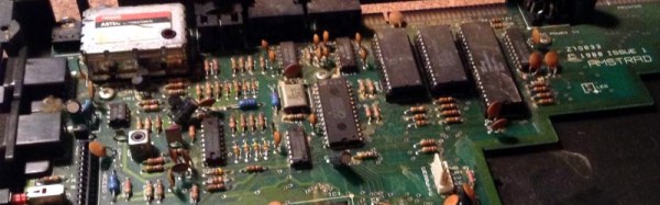
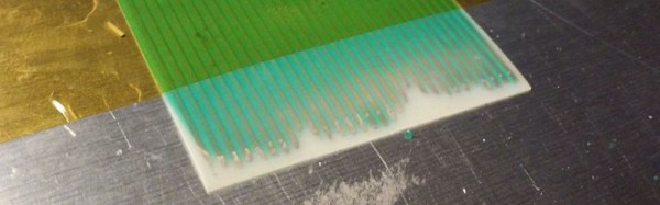
Wiring a PSU to a DIN plug for a retro computer is not an exceptional piece of work in itself even if it’s tidily done and nice to see older hardware brought back to life. What makes this piece worth a look instead is the teardown of what is a slightly unusual footnote to the 8-bit home computer story. We’re shown the familiar Z80 and support chips with the Spectrum edge connector and modulator on a through-hole board with a piece of cutting edge tech for a 1980s home computer, a single SMD chip unusually mounted nestled in a hole cut in the board.
Amstrad eventually stopped making Spectrums in the early 1990s, having also tried the Sinclair name on a spectacularly awful PC-compatible home computer. [Clive Sinclair] continued to release electronic products over the following decades, including a portable computer, the last of his trademark miniature radio receivers, and an electric bicycle accessory. Amstrad continue to make computers to this day, and [Alan Sugar] has achieved fame of a different sort as host of the UK version of The Apprentice. He has not yet become Prime Minister.
We’ve featured another Amstrad Spectrum +2 losing its tape deck for a slimmer machine. On that note, the Spectrum wasn’t Amstrad’s only entry in the 8-bit market, and we’ve also shown you a compact clone of their CPC464. As for [Drygol], he’s featured here several times. His mass-restoration of Commodore 64s for instance, or bringing a broken Atari ST back from the dead.
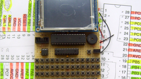
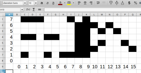
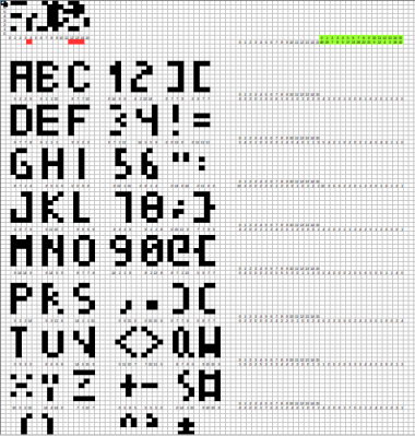 Rather than a pixel-by-pixel representation of the characters, [Jaromir] created a palette of 16 single byte vectors of commonly used patterns. Characters are created by combining these vectors. Each character is 4 x 8 pixels, so 4 vectors are used per character. The hard part was picking commonly used bit patterns for the vectors.