
Not that it’s the kind of thing that pops into your head often, but if you ever do think of a cyanotype print, it probably doesn’t conjure up thoughts of modern technology. For good reason — the monochromatic technique was introduced in the 1840s, and was always something of a niche technology compared to more traditional photographic methods.
The original method is simple enough: put an object or negative between the sun and a UV-sensitive medium, and the exposed areas will turn blue and produce a print. This modernized concept created by [Gabe] works the same way, except both the sun and the negative have been replaced by a lightly modified resin 3D printer.
 A good chunk of the effort here is in the software, as [Gabe] had to write some code that would take an image and turn it into something the printer would understand. His proof of concept was a clever bit of Python code that produced an OpenSCAD script, which ultimately converted each grayscale picture to a rectangular “pixel” of variable height. The resulting STL files could be run through the slicer to produce the necessary files to load into the printer. This was eventually replaced with a new Python script capable of converting images to native printer files through UVtools.
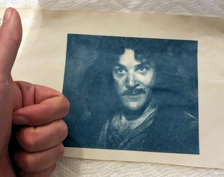
On the hardware side, all [Gabe] had to do was remove the vat that would usually hold the resin, and replace that with a wooden lid to both hold the UV-sensitized paper in place and protect the user’s eyes. [Gabe] says there’s still some room for improvement, but you wouldn’t know it by looking at some of the gorgeous prints he’s produced already.
No word yet on whether or not future versions of the project will support direct-to-potato imaging.


