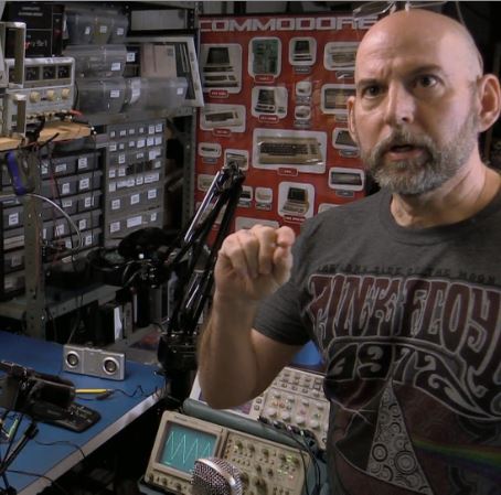
To celebrate the 40th anniversary of CP/M, the Computer History Museum has released a package containing early source code for several versions of CP/M. Originally designed by [Gary Kildall] in 1973, Control Program for Microcomputers (CP/M) is an early operating system for microprocessor based computers. The OS was originally written for the Intel Intellec 8, an Intel 8008 based computer. Since it was on an Intel machine, CP/M was written in PL/M (Programming Language for Microcomputers), a language [Kildall] had previously developed for Intel .
CP/M pioneered the idea of a ROM based Basic Input Output/System (BIOS) for commonly used routines on a given computer. The use of BIOS made CP/M easy to port. Eventually it was ported to thousands of different machines and architectures, including the Altair, IMSAI 8080, C-64, and C-128 and Apple II systems.
Gary and his company Digital Research, were one of the top contenders for the operating system on IBM’s new personal computer. Ultimately, Microsoft got the job by purchasing 86-DOS from Seattle Computer Products. Somewhat ironically, 86-DOS itself was written based on the CP/M Application Programming interface (API).
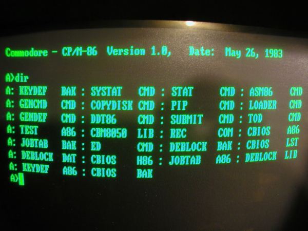
The source itself is an amazing trip back in time. Included are portions of CP/M 1.1, 1.3, 1.4, and 2.0. Portions of CP/M have been released previously. As with the previous files, this version includes modifications performed by z80-pack author [Udo Munk] in 2007. Version 1.3 is especially interesting as it is primarily scanned copies of the CP/M source code.
If you’re into vintage computing, and know how important CP/M was to the early days of personal computers, check out the CP/M source. If you find any interesting or clever bits of code, be sure let us know about it in the comments.
[Image Source: CulturaInformatica]
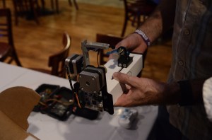 [Windell and Lenore] from Evil Mad Scientist Laboratories brought a few hacks along. They picked up an old Radio Shack music player chip at the
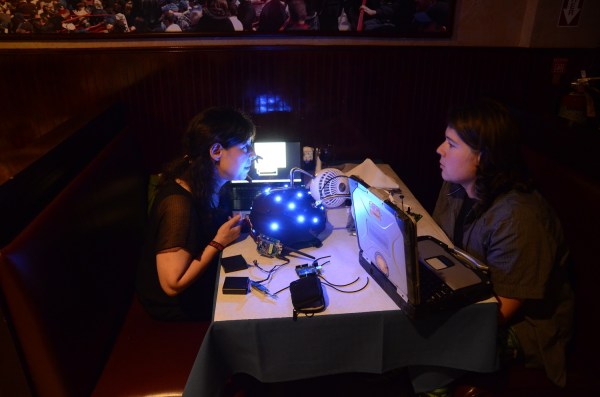
 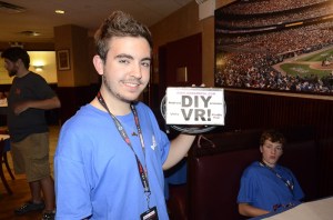 [Cal Howard] brought his DIY VR goggles. [Cal] converted a Kindle Fire into an Oculus Rift style head mounted display by adding a couple of magnifying lenses, some bamboo kebab sticks to hold the lenses in place. Judicious use of cardboard and duct tape completed the project. His current hurdle is getting past the Fire’s lack of an accelerometer. [Cal] planned to spend Sunday at Maker Faire


