Released in 2002, Apple’s iMac G4 was certainly a unique machine. Even today, its hemispherical case and integrated “gooseneck” display is unlike anything else on the market. Whether or not that’s a good thing is rather subjective of course, but there’s no denying it’s still an attention grabber nearly 20 years after its release. Unfortunately, it’s got less processing power than a modern burner phone.
Which is why [Tom Hightower] figured it was the perfect candidate for a retrofit. Rather than being little more than a display piece, this Intel NUC powered iMac is now able to run the latest version of Mac OS. He even went as far as replacing the display with a higher resolution panel, though it sounds like it was dead to begin with so he didn’t have much choice in the matter.
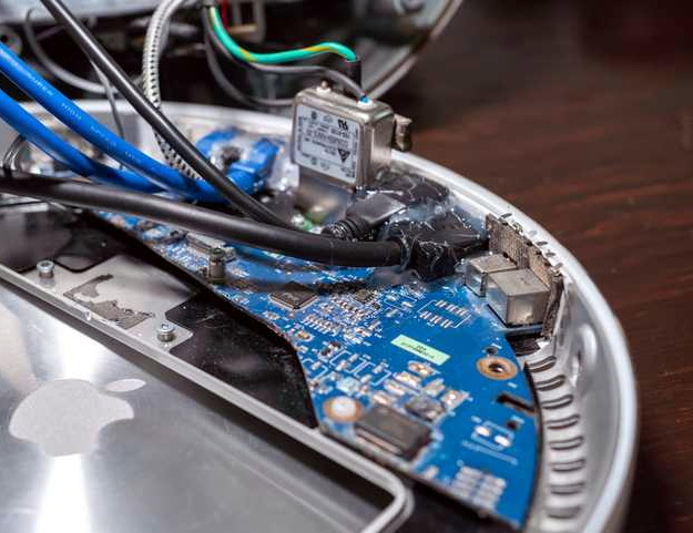
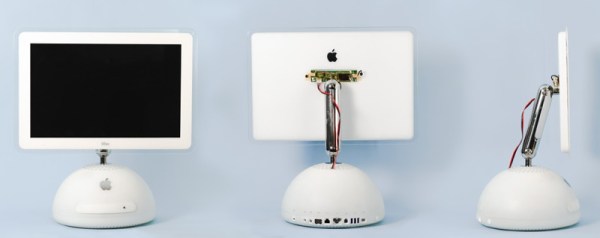
The retrofit starts off with a brief teardown, which is quite interesting in itself. [Tom] notes a number of unique design elements, chief among them the circular motherboard. The two banks of memory also use different form factors, and only one of them is easily accessible to the end user. Something to think about the next time somebody tells you that Apple’s “brave” hardware choices are only a modern phenomena.
There was plenty of room inside the iMac’s dome to fit the NUC motherboard, and some extension cables and hot glue got the computer’s rear panel suitably updated with the latest-and-greatest ports and connectors. But the conversion wasn’t a total cakewalk. That iconic “gooseneck” put up quite a fight when it was time to run the new wires up to the display. Between the proprietary screws that had to be coerced out with a Dremel to the massive spring that was determined to escape captivity, [Tom] recommends anyone else looking to perform a similar modification just leave the wires on the outside of the thing. That’s what he ended up doing with the power wires for the display inverter.
If you like the idea of reviving old Apple hardware but don’t want to anger the goose, you could start on something a little easier. Like putting an iPad inside of a Macintosh Classic shell.

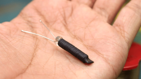
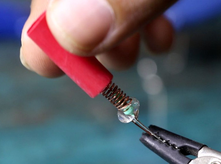
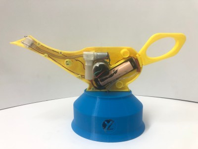 The lamp body consists of two 3D-printed halves held together by neodymium magnets. They house a 400 kV spark generator, a fuel pump plus tank, and a 18650 Li-ion battery. The fuel pump is actually a 3 V air pump but it can also pump liquids at low pressure. As fuel [YeleLabs] used rubbing alcohol that they mixed with boric acid to give the flame a greenish tint. The blue base at the bottom of the lamp houses the triggering mechanism which magically lights up the lamp when you snap your fingers. This is achieved by a KY-038 microphone module and KY-019 relay module connected to a Digispark ATTiny85 microcontroller. When the microphone signal is above a certain threshold the relay module will simultaneously switch on the spark generator and fuel pump for 150 ms.