Hackers and makers have built just about every kind of clock under the sun. Digital, analog, seven-segment, mechanical seven-segment, binary, ternary, hexadecimal… you name it. It’s been done. You really have to try to find something that shocks us… something we haven’t seen before. [Moritz v. Sivers] has done just that.
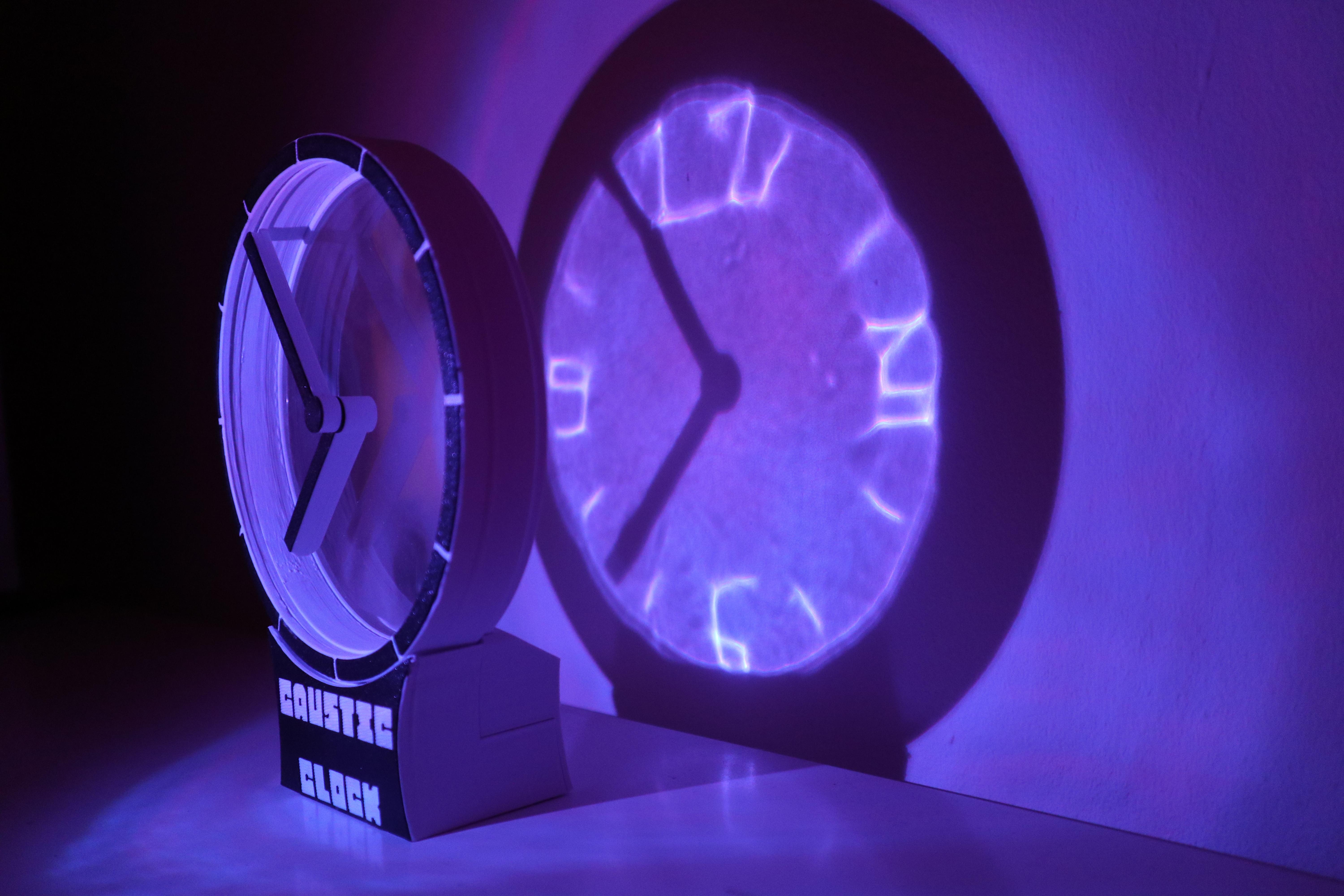
Meet the Caustic Clock. It’s based on the innovative Hollow Clock from [shiura]. It displays time with an hour hand and a minute hand, and that’s all so conventional. But what really caught our eye was the manner in which its dial works. It uses caustics to display the clock dial on a wall as light shines through it.
If you’ve ever seen sunlight reflect through a glass, or the dancing patterns in an outdoor swimming pool, you’ve seen caustics at play. Caustics are the bright patterns we see projected through a transparent object, and if you shape that object properly, you can control them. In this case, [Moritz] used some GitHub code from [Matt Ferraro] to create a caustic projection clockface, and 3D printed it using an SLA printer.
The rest of the clock is straightforward enough—there’s some WS2812 LEDs involved, an Arduino Nano, and even an RP2040. But the real magic is in the light show and how it’s all achieved. We love learning about optics, and this is a beautiful effect well worth studying yourself.
Continue reading “Innovative Clock Uses Printed Caustic Lens”