NTP is one of the most interesting and important, but all too forgotten, protocols that makes the internet tick. Accurate clock synchronization is required for everything ranging from cryptography to business and science. NTP is closely tied around a handful of atomic clocks, some in orbit on GPS satellites, and some in laboratories. So the near-failure of one such atomic clock sparked a rather large, and nerdy, internet debate.
On December 17, 2025, the Colorado front range experience a massive wind storm. The National Center for Atmospheric Reassure in Boulder recorded gusts in excess of 100 mph (about 85 knots or 160 kph). This storm was a real doozy, but gusts this strong are not unheard of in Boulder either. That is no small reason the National Renewable Energy Laboratory (now the National Laboratory of the Rockies) has a wind turbine testing facility in the neighborhood.
Currently quartz crystal-based oscillators are among the most common type of clock source in electronics, providing a reasonably accurate source in a cheap and small package. Unfortunately for high accuracy applications, atomic clocks aren’t quite compact enough to fit into the typical quartz-based temperature-compensated crystal oscillators (TCXOs) and even quartz-based solutions are rather large. The focus therefore has been on developing doped silicon MEMS solutions that can provide a similar low-drift solution as the best compensated quartz crystal oscillators, with the IEEE Spectrum magazine recently covering one such solution.
Part of the DARPA H6 program, [Everestus Ezike] et al. developed a solution that was stable to ±25 parts per billion (ppb) over the course of eight hours. This can be contrasted with a commercially available TCXO like the Microchip MX-503, which boasts a frequency stability of ±30 ppb.
Higher accuracy is achievable by swapping the TCXO for an oven-controlled crystal oscillator (OCXO), with the internal temperature of the oscillator not compensated for, but rather controlled with an active heater. There are many existing OCXOs that offer down to sub-1 ppb stability, albeit in quite a big package, such as the OX-171 with a sizable 28×38 mm footprint.
With a MEMS silicon-based oscillator in OXCO configuration [Yutao Xu] et al. were able to achieve a frequency stability of ±14 ppb, which puts it pretty close to the better quartz-based oscillators, yet within a fraction of the space. As these devices mature, we may see them eventually compete with even the traditional OCXO offerings, though the hyperbolic premise of the IEEE Spectrum article of them competing with atomic clocks should be taken with at least a few kilograms of salt.
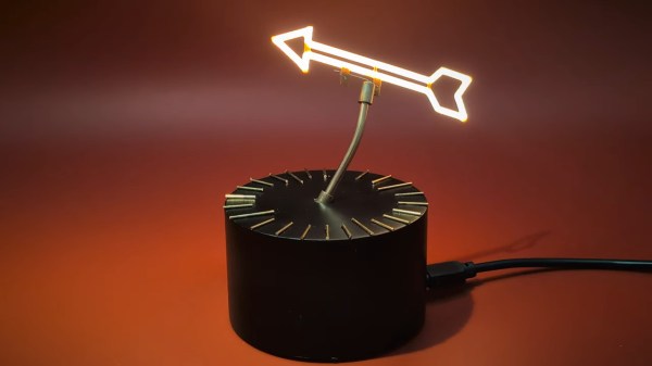
The Dutch word for sundial, zonnewijzer, can be literally translated into “Sun Pointer” according to [illusionmanager] — and he took that literal translation literally, building a reverse sundial so he would always know the precise location of our local star, even when it is occluded by clouds or the rest of the planet.
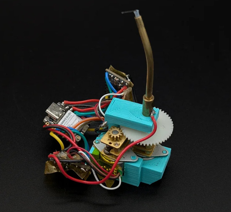
The electronics aren’t hugely complicated: an ESP32 dev board, an RTC board, and a couple of steppers. But the craftsmanship is, as usual for [illusionmanager], impeccable. You might guess that one motor controls the altitude and the other the azimuth of the LED-filament pointer (a neat find from AliExpress), but you’d be wrong.
This is more like an equatorial mount, in that the shaft the arrow spins upon is bent at a 23.5 degree angle. Through that hollow shaft a spring-steel wire connects the arrow to one stepper, to drive it through the day. The second stepper turns the shaft to keep the axis pointed correctly as Earth orbits the sun. See the demo video embedded below for full details.
Either way you can get an arrow that always points at the sun, but this is lot more elegant than an alt-az mount would have been, at the expense of a fiddlier build. Given the existence of the orrery clock we featured from him previously, it’s safe to say that [illusionmanager] is not afraid of a fiddly build. Doing it this way also lets you read the ticks on the base just as you would a real sundial, which takes this from discussion piece to (semi) usable clock.
We love a good clock project, and [byeh_ in] has one with a design concept we don’t believe we have seen before. The Trace Line Clock has smooth lines and a clean presentation, with no sockets or visible mechanical fixtures.
Reading the clock is quite straightforward once one knows what is going on. At its heart, the unmarked face is much like any other analog clock face, and on the inside is a pretty normal clock movement. The inner recessed track on the face represents hours, and the outer is minutes. The blue line connects the two, drawing a constantly changing line.
One easy way to make a very accurate clock is with a WiFi-enabled microcontroller like an ESP32 and a display: set up NTP, and you’ll never be off by more than a minute. This water clock project by [Liebregts] is not like that — there are no electronics to speak of, and if the clock is ever in sync to within a single minute, well, we’d be surprised.
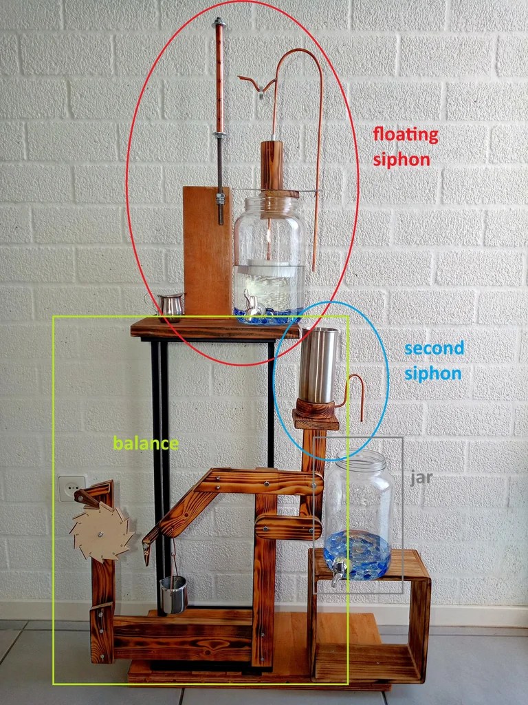
We’re impressed to see it working regardless. Sure, it’s not exactly high-tech; the floating siphon mechanism [Liebregts] is using to get a steady flow out of the main reservoir dates back to 250 BC. On the other hand, since this style of time keeper has been out of fashion since the fall of Rome, [Liebregts] couldn’t just grab something off GitHub or ask ChatGPT to design it for them. This is real human engineering. The reservoir is even scaled to the four-hour timing of [Liebregts] workday — it gets refilled at lunch along with its maker.
The water clock in all its glory, plus diagrammatic labels.
In a clever build detail, the floating siphon tube also holds a pointer to an hour indicator. For minutes, his mechanism seems unique, though it’s related to another ancient trick, the Pythagorean cup. Pythagoras’s devious cup had a hidden siphon that spilled its contents if you filled it beyond a set level, and so does the secondary reservoir of [Liebregts] water clock.
Since the secondary reservoir is linked to a counterweight with a pivot, it goes up and down over the course of approximately 5 minutes — but rather than linking that to another linear indicator, [Liebregts] is using that mechanism to advance a saw-toothed gear that is marked with 5-12 in analog-clock fashion for a touch of modernity. See it in action in the demo video below.
That last part might confuse a time traveler from Ancient Rome or Greece, but they’d instantly recognize this creation as a clock, which many modern observers might not. Still, once they learn to read it you can be sure that [Liebergts]’s friends will never be late to a gladiator fight again — and not just because Constantine banned them in 325 AD. Apparently nobody listened to that ban anyway.
Assuming you’re not stuck in a prison cell without windows, you could feasibly keep track of the moon and tides by walking outside and jotting things down in your notebook. Alternatively, you could save a lot of hassle by just building this moon and tide clock from [pjdines1994] instead.
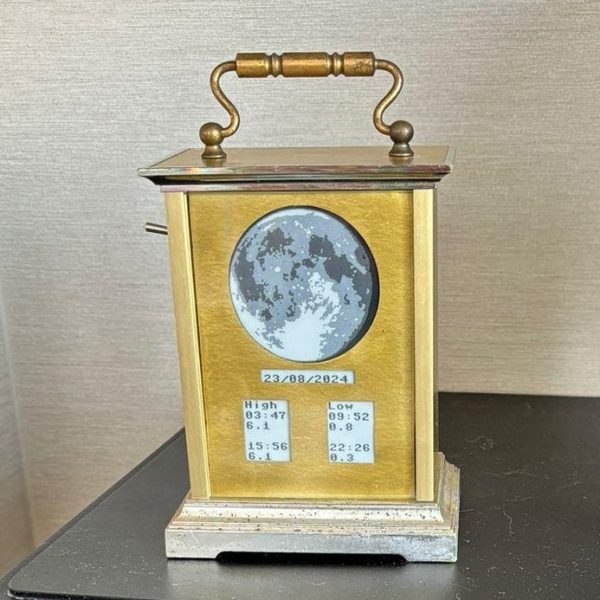
The build is based on a Raspberry Pi Pico W, which is hooked up to a real-time clock module and a Waveshare 3.7-inch e-paper display. Upon this display, the clock draws an image relevant to the current phase of the moon. As the write-up notes, it was a tad fussy to store 24 images for all the different lunar phases within the Pi Pico, but it was achieved nonetheless with a touch of compression. As for tides, it covers those too by pulling in tide information from an online resource.
It’s specifically set up to report the local tides for [pjdines1994], reporting the high tide and low tide times for Whitstable in the United Kingdom. If you’re not in Whitstable, you’d probably want to reconfigure the clock before using it yourself. Unless you really want to know what’s up in Whitstable, of course. If you so wish, you can set the clock up to make its own tide predictions by running local calculations, but [pjdines1994] notes that this is rather more complicated to do. The finished result look quite good, because [pjdines1994] decided to build it inside an old carriage clock that only reveals parts of the display showing the moon and the relevant tide numbers.
We’ve featured some other great tide clocks before, like this grand 3D printed design. If you’ve built your own arcane machine to plot the dances of celestial objects, do be sure to let us know on the tipsline!
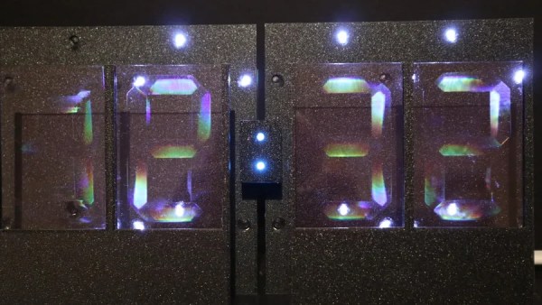
The first step was to make the holographic segment displays, because they’re not really something you can just buy off the shelf. [mosivers] achieved this by using a kit from LitiHolo, which enables you to create holograms by shooting a laser at special holographic film. Only, a few upgrades were made to use the kit with a nicer red diode laser that [mosivers] had on hand for better performance. The seven-segment layouts were carefully recorded on to the film to form the basic numerals of the clock, such that illuminating the films from different angles would light different segments of the numeral. It’s quite involved, but it’s explained well in the build video.
As for the timekeeping side of things, an ESP32 was used, setup to query a network time server to stay accurate. The microcontroller then commands a series of LEDs to light up as needed to illuminate the relevant segments of the holographic film to show the time.
Ultimately, [mosivers] built a cool clock with a look you won’t find anywhere else. It’s a lot more work than just wiring up some classic seven-segment LEDs, but we think the result is worth it. If you fancy other weird seven-segment builds, though, we’ve got plenty of others in the till.