A Real-Time Networked VU Running On The ESP8266

Even though the ESP8266 WiFi chipsets are really cheap (and can be somewhat challenging to work with), they still pack a lot of processing power. For instance, [Mr.jb.swe] took one of these modules and made a stand-alone live VU meter with WS2812B LED strip. The VU runs entirely on the ESP chip, without any additional microcontroller. It’s an example we think a lot of projects could follow to do away with unused horsepower (extra microcontrollers) sometimes used to avoid programming directly on the ESP. The stuff you can do with these modules is wild… did you see this WiFi signal strength mapping project?

The ESP chipset acts as a UDP client which receives packets from a WinAmp plugin that [Mr.jb.swe] wrote. The plugin continuously calculates the dB of whatever track is playing and streams it over WiFi to his ESP8266. He also mentions that the ADC of the ESP chipset could be used to sample audio as well, although that pretty much eliminates the need for WiFi.

The whole setup is very responsive even though the processor is parsing UDP messages, driving the WS2812 strip, and driving a small OLED display for debug—and it doesn’t even use a separate microcontroller. [Mr.jb.swe] also posted snippets of his code to get you started on your own project. Check out the videos after the break to see it in action.

Continue reading “A Real-Time Networked VU Running On The ESP8266”

Clocked 8-Bit Random Pattern Generator For A CMOS Synth

A random noise generator is pretty handy when working with music, and building one using a micro-controller can be pretty trivial. So it’s nice when someone comes along and builds it from a few analog and digital parts. [acidbourbon] built his Clocked 8-BIT Random Pattern Generator for  CMOS Synth  inspired and motivated by the recent article Logic Noise: Sweet, Sweet Oscillator Sounds by [Elliot Williams]. It’s 8-bit output can be used as a random sequencer for DIY CMOS synths.
This pattern generator is suited to to be used in combination with a 4051 8-channel analog multiplexer. But it sounds quite interesting on it’s own (best enjoyed in stereo, check out the video after the break). After building some CMOS synth circuits, [acidbourbon] moved on to make some sequencers and multiplexers which then let him to devise this random pattern generator which could be gated using a clock signal.

The basic principle is straight forward – generate noise, amplify it, apply a clock to get the gated noise output. His design choices for the various sections are well explained, based on constraints that he had to work with. Everything needs to work at 5V, but his noise generator circuit requires 12V to work. He choose to use a charge pump to generate -5V, resulting in a 10V supply, which was barely enough, but worked. A boost regulator might probably have served better to generate 12V, but maybe he already had the ICL7660 charge pump IC lying around in his parts bin. The rest of the circuit uses standard CMOS/TTL devices, and [acidbourbon] provides all of the design files for what looks like a neat, single sided PCB that can easily be made using the toner-transfer method.

Video below.

Continue reading “Clocked 8-Bit Random Pattern Generator For A CMOS Synth”

Logic Noise: Sweet, Sweet Oscillator Sounds

Welcome to part one of a series taking you down the rabbit hole of DIY electronic synthesizers based on (largely) CMOS logic chips. Instead of synths being commodity gear made by large corporate enterprises, we’ll be building with the cheapest available parts, using and misusing digital logic. In short, don’t expect pre-packaged smooth tones, because we’ll be making creative noise machines.

If you’re the chiptunes type, you’ll probably find something you like here. If you’re the circuit bender or electro-noise-punk type, this is gonna be right up your alley. If you just like to see CMOS chips wriggle and squirm in unintended ways, feel free to look over my shoulder. If you’re the type who insists that a screwdriver can’t be used to pry open a paint can, then maybe you’d better move along. There’s a thin line between the glitch as bug and the glitch as interesting discovery, and we’ll be dancing all over it.

Continue reading “Logic Noise: Sweet, Sweet Oscillator Sounds”

backpack stereo

SnoTunes Lets You Rock Out In The Winter

[Matt Bilsky], an avid reader of Hackaday for years, finally gathered up the courage to submit a project to us. We swear, we don’t byte! Anyway — we’re glad he did, because his project is absolutely awesome. He calls it SnoTunes and it’s a backpack stereo system designed for the outdoors.

It’s a whopping 160 watt stereo, has 7-8 hours of battery life, is somewhat water resistant, and can be controlled wirelessly. Its brain is a Raspberry Pi B+ running Kodi (which was formerly XBMC). A 7″ display is hidden inside of the backpack for more fine tuning controls.

It fetches and downloads YouTube music videos and can create a playlist that can be manipulated by text message. You can share YouTube links to have it download and queue the songs, you can skip the songs (but only if four people make the request), and it even automatically parses the music video titles to extract the song name and band. It also works with AirPlay — but who even uses that.

Continue reading “SnoTunes Lets You Rock Out In The Winter”

DIY USB Stereo Headphone Amplifier

The biggest and best audiophile projects are usually huge tube amps, monstrous speaker cab builds, or something else equally impressive. It doesn’t always have to be that way, though, as [lowderd] demonstrates with a tiny DIY USB DAC build that turns a USB port into a headphone output.

In the Bad Old Days™ putting a DAC on a USB bus would require some rather fancy hardware and a good amount of skill. These days, you can just buy a single chip USB stereo DAC that still has very good specs. [lowderd] used the TI PCM2707 USB DAC, a chip that identifies as a USB Audio Class 1.0 device, so no drivers are needed for it to work in either Windows or OS X.

The circuit fits on a tiny PCB with a USB port on one side, a headphone jack on the other, and the chip and all related components in between. There are some pins on the chip that allow for volume, play/pause. and skip, but these pins were left unconnected for sake of simplicity.

The board was fabbed up at OSH Park, and the second revision of the case laser cut out of bamboo and acrylic by Ponoko. It’s a great looking little box, and something that fits right inside [lowderd]’s headphone case.

Learning Python With Tron Radio

[5 Volt Junkie] has built his share of Arduino projects, but never anything with Python, and certainly never anything with a GUI. After listening to Internet radio one day, a new idea for a project was born: a Raspberry Pi with a small touchscreen display for a UI and displaying soma.fm tracks. It’s finally finished, and it’s a great introduction to Python, Pygame, and driving tiny little displays with the Pi.

Playing soma.fm streams was handled by mpd and mpc, while the task of driving a 2.8″ TFT LCD was handled by the fbtft Linux framebuffer driver. This left [5 Volt Junkie] with the task of creating a GUI, some buttons, and working out how to play a few streams. This meant drawing some buttons in Inkscape, but these were admittedly terrible, so [5 Volt Junkie] gave up and turned on the TV. Tron Legacy was playing, giving him the inspiration to complete his Tron-themed music player.

The result of [5 Volt Junkie]’s work is a few hundred lines of Python with Pygame and a few multicolor skins all wrapped up in a Tron theme. It looks great, it works great, and it’s a great introduction to Python and Pygame.

Continue reading “Learning Python With Tron Radio”

Digital To Analog To Digital To Analog To Digital Conversion

[Andy] had the idea of turning a mixing desk into a MIDI controller. At first glance, this idea seems extremely practical – mixers are a great way to get a lot of dials and faders in a cheap, compact, and robust enclosure. Exactly how you turn a mixer into a MIDI device is what’s important. This build might not be the most efficient, but it does have the best name ever: digital to analog to digital to analog to digital conversion.

The process starts by generating a sine wave on an Arduino with some direct digital synthesis. A 480 Hz square wave is generated on an ATTiny85. Both of these signals are then fed into a 74LS08 AND gate. According to the schematic [Andy] posted, these signals are going into two different gates, with the other input of the gate pulled high. The output of the gate is then sent through a pair of resistors and combined to the ‘audio out’ signal. [Andy] says this is ‘spine-crawling’ for people who do this professionally. If anyone knows what this part of the circuit actually does, please leave a note in the comments.

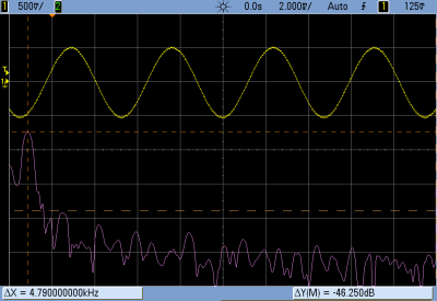
The signal from the AND gates is then fed into the mixer and sent out to the analog input of another Arduino. This Arduino converts the audio coming out of the mixer to frequencies using a Fast Hartley Transform. With a binary representation of what’s happening inside the mixer, [Andy] has something that can be converted into MIDI.

[Andy] put up a demo of this circuit working. He’s connected the MIDI out to Abelton and can modify MIDI parameters using an audio mixer. Video of that below if you’re still trying to wrap your head around this one.

Continue reading “Digital To Analog To Digital To Analog To Digital Conversion”