S/PDIF has been around for a long time; it’s still a really great way to send streams of digital audio from device A to device B. [Nathan Ladwig] has got the ESP32 decoding SPDIF quite effectively, using an onboard peripheral outside its traditional remit.
On the ESP32, the Remote Control Transceiver (RMT) peripheral was intended for use with infrared transceivers—think TV remotes and the like. However, this peripheral is actually quite flexible, and can be used for sending and receiving a range of different signals. [Nathan] was able to get it to work with S/PDIF quite effectively. Notably, it has no defined bitrate, which allows it to work with signals of different sample rates quite easily. Instead, it uses biphase mark code to send data. With one or two transitions for each transmitted bit, it’s possible to capture the timing and determine the correct clock from the signal itself.
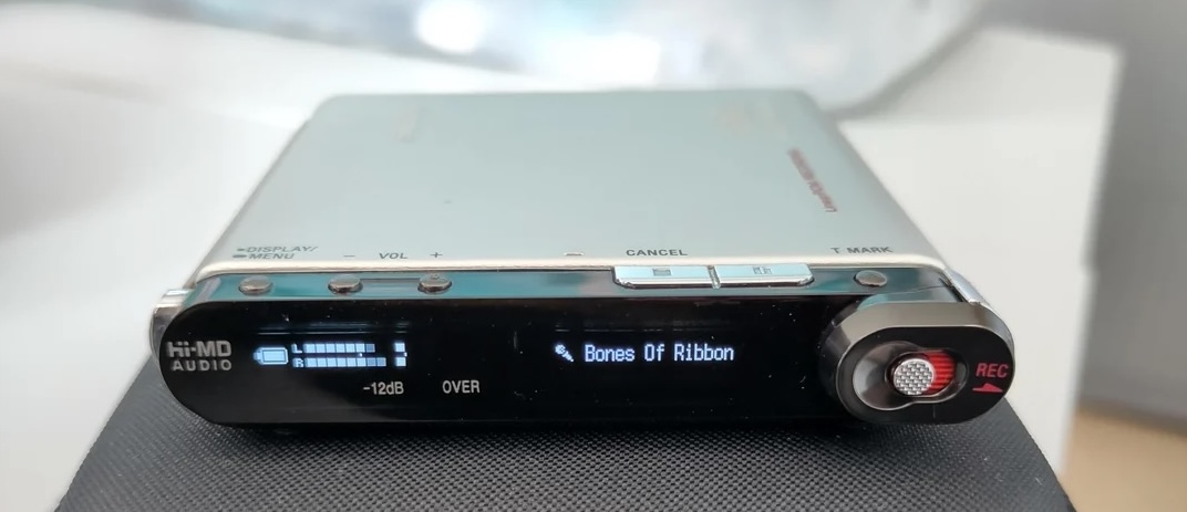
[Nathan] achieved this feat as part of his work to create an ESP32-based RTP streaming device. The project allows an ESP32 to work as a USB audio device or take an S/PDIF signal as input, and then transmitting that audio stream over RTP to a receiver which delivers the audio at the other end via USB audio or as an SPDIF output. It’s a nifty project that has applications for anyone that regularly finds themselves needing to get digital audio from once place to another. It can also run a simple visualizer, too, with some attached LEDs.
It’s not the first time we’ve seen S/PDIF decoded on a microcontroller; it’s quite achievable if you know what you’re doing. Meanwhile, if you’re cooking up your own digital audio hacks, we’d love to hear about it. Digitally, of course, because we don’t accept analog phone calls here at Hackaday. Video after the break.
Continue reading “ESP32 Decodes S/PDIF Like A Boss (Or Any Regular Piece Of Hi-Fi Equipment)”