Graphing calculators have evolved from expensive playthings for rich nerds to everyday tools for high schoolers worldwide. Even though teenagers nowadays carry powerful internet-connected computers in their pockets, math teachers often prefer them to use a clunky Z80-powered calculator in class, if only because their limited performance reduces the potential for distraction. The worst thing a lazy student can do is play a simple game like Snake or Tetris.
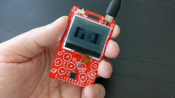
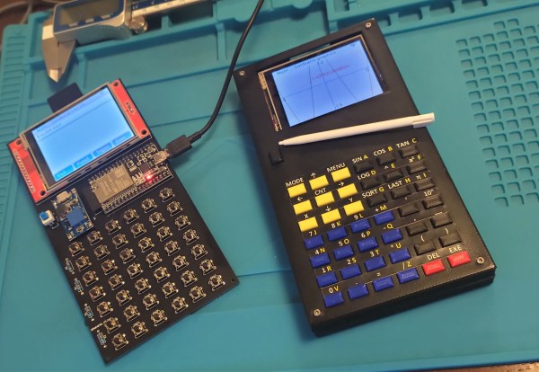
But what if you’re not a student anymore and you want a graphing calculator that has up-to-date hardware and infinite customizability in software? Look no further than [Angel Cabello]’s Galdeano, a handheld that has all the features of a modern graphing calculator plus a lot more. The heart of the device is an ESP32, which sits on a custom PCB that also holds a 6×7 array of push-buttons and a 320×240 touch-sensitive color display. It can be powered through a lithium-polymer battery or, like a classic calculator, through four AAA cells. The entire thing is housed in a 3D printed enclosure with color-coded buttons indicating various built-in functions.
 The ESP32 runs MicroPython along with a symbolic math engine called Eigenmath. This enables the Galdeano to manipulate expressions, perform integration and differentiation, and plot functions. Porting Eigenmath to a memory-constrained platform like the ESP32 was quite a challenge and required a few workarounds, including a memory partition scheme and even a custom compact font with mathematical symbols.
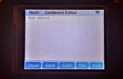
Thanks to the flexibility of MicroPython and the ESP’s WiFi system, the Galdeano is not limited to implementing a calculator: it can also perform various general-purpose tasks ranging from file editing to controlling a set of smart light bulbs. The project page doesn’t mention any games yet, but we’re sure it won’t take long before someone ports Tetris to this system as well.
Of course, even classroom-grade calculators can be pushed to do much more than their designers intended: they can receive GPS signals, run Debian or even perform ray tracing. If you’re looking for a powerful open-source calculator, this BeagleBoard-based machine runs the R statistical computing environment.
Continue reading “2022 Cyberdeck Contest: The Galdeano Is More Than A Graphing Calculator”