Update: Testing The Accuracy Of A Magnetic Rotary Encoder

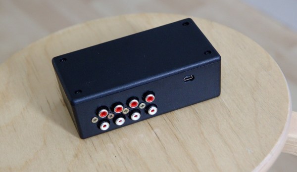
A while back we featured a magnetic rotary encoder that [LongHairedHacker] designed. The heart of the system is an AS5043 magnetic rotary sensor which runs from $6.5-$11 and has a 10 bits precision. As we wanted to check if his design was really efficient, he made a test bench for it.

For 360 degrees, a 10 bits precision means a ±0.175º accuracy, which is quite impossible to check with conventional measurement equipment. The first approach he thought of was to attach a mirror to the encoders axis and point a laser beam at it. The laser beam would be reflected across the room to a big scale, but the minimum required distance would have been 5 meters (16 feet). So he preferred attaching a motor to the sensor, rotating at a given speed and measuring the sensor output.

In the first part of his write-up, [LongHairedHacker] lays the math which explains the different kinds of errors that should be expected from his setup and sensor. He then proceeds with his test, where an ATMEGA8 based board is used to send the measured position to his computer. It should be noted that [LongHairedHacker] currently uses the time spent between two received measurements on his computer as a time base, but he is planning on time stamping the data on his board in the next future. Nevertheless, he managed to measure an average ±0.179º accuracy with his simple test bench, which is very close to the manufacturer specification.

Here is the link to our original post about his sensor.

Reverse-engineering Old Finnish Metro Station Displays

This project definitely was a patience tester. As the control system of the Helsinki metro was (and still is) under big renovation, [Konsta] could buy three old information displays for a very cheap price (5€ each). However, these displays came with no information whatsoever about the way to drive them, thus starting a long reverse-engineering journey.

[Konsta] started by taking one apart, discovering that each side of the display was composed of 10 daisy-chained LCD screens and some kind of control box. As you may have guessed, the key to reverse engineering the display was studying the contents of this box. It turned out that the control electronics were composed of an 8085 CPU, some RAM, a peripheral I/O chip, an UV-erasable EPROM chip (containing 32KB of program memory) and an EEPROM.

[Konsta] used an AVR to dump the memory contents of the two latter chips and it was at this part of the project that the Helsinki Hacklab joined in. Together, they reverse engineered the control PCB, studied the assembler code, sniffed the different on-board buses to fully understand how the display could be controlled.

We strongly recommend reading [Konsta]’s writeup, especially knowing that he made this english page just for us!

Getting SPI On A Router

router

Cheap routers such a s the TP-LINK 703n and the TP-LINK MR3020 (seen above) can be used for much more than just connecting your laptop to your cable modem. They’re actually very small Linux boxes and with OpenWRT, you can control every aspect of these tiny pocket-sized computers. It’s frequently been suggested that these routers are awesome substitutes for the usual methods of getting Internet on a microcontroller, but how do you actually do that? The onboard serial port is a great start, but this also dumps output from the Linux console. What you need here is an SPI connection, and [ramcoderdude] has just the solution for you.

Linux already has a few SPI modules, but these are only accessible with kernel drivers. Traditionally, the only way to access SPI is to recompile the kernel, but [coderdude] created a kernel module that allows any device running the Attitude Adjustment OpenWRT image to dynamically allocate SPI busses.

He’s already submitted this patch to the OpenWRT devs, and hopefully it will be included in future updates. Very cool, we think, and something that can open a whole lot of doors for hacking up routers very easily.

Electronic Wedding Attire For A Geeky Wedding

In the past we featured many projects that were used at [Bill] and [Mara]’s wedding. However we forgot the most important thing: their electronically enhanced clothes.

As you can see from the picture above, the wife opted for LEDs while the husband preferred Electro Luminescent (EL) wires/panels. The ATtiny based platform LilyTiny was picked to control all the LEDs, and charlieplexing was implemented as only 4 IO pins were available. Animations were made using Vixen and exported via a python script.

To power the EL wires, [Bill] hacked a Sparkfun EL battery pack/inverter. He removed the shell and took out the inverter part, reverse engineered the design enough to figure out how to bypass the onboard microcontroller that generated the on/off/blink function. Finally, he 3D printed enclosures to pack the electronics with one Li-Ion battery pack. A boost regulator was used to supply the 12v required by the EL panel power supply.

Don’t forget to also check out their centerpieces and wedding invitations that we previously featured.

Making The Electronics For A Doppler Motion Sensor

There are many different sensors that can be used to detect motion in a given environment. Passive InfraRed (PIR) sensors are the most used today, as they work by detecting moving heat signatures. However, they are less reliable in the hotter days and obviously only work for animals and humans.

Sensors like the one shown in the above picture started to appear on the internet, they use the doppler effect to detect motion. I (limpkin) designed the electronics you need to add in order to get them to work.

Here is a simple explanation of the doppler effect: if you send an RF signal at a given frequency to a moving target, the reflected signal’s frequency will be shifted. It is commonly heard when a vehicle sounding a siren or horn approaches, passes, and recedes from an observer. The received frequency is higher (compared to the emitted frequency) during the approach, it is identical at the instant of passing by, and it is lower during the recession. Continue reading “Making The Electronics For A Doppler Motion Sensor”

Playing With An Oscilloscope You’ll (probably) Never Own

We’ll have to admit that we were really jealous when [Shahriar] sent us a video he made, in which he casually explains how a $500,000 160GS/s 62GHz oscilloscope works and then starts playing with it.

Even though you need to be quite familiar with electronics to fully understand the oscilloscope’s inner workings, [Shahriar]’s step by step explanation is still approachable for those who only understand the basics.

In the first half of the video he uses the manufacturer’s documentation which contains the oscilloscope block diagrams, so you’ll also learn about:

  • timer interleaved Analog to Digital Converters (ADCs), which allows you to increase your input sampling rate by using several of them
  • phase-locked loops, which use a reference clock to generate a much faster clock signal
  • custom made dies and the materials used for high frequency electronic components

In the second half of the video [Shahriar] connects a pseudo random binary sequence generator and uses the oscilloscope to make several measurements that you’d typically want to know for high speed signals (jitters, eye quality factor…). He later performs a small experiment where he up-converts the frequency components of two random 3.12Gbit/s signals and tries to recall each original signal using the oscilloscope functions, making this part of the video a bit harder to keep up with.

Designing A Pressure Sensitive Floor

ccm_activefloor8

[Sean] and his team at Adobe were asked to build “something new” for the Children’s Creativity Museum in San Francisco, so in several months they managed to build a digital/physical environment for kids called “Sense It”.

Part of this project involved designing and building a pressure-sensitive electronic floor which could detect if children were sitting, walking or running. As a camera based detection system couldn’t give them the type of precision they wanted, [Sean] decided to use pressure-sensitive resistors placed under MDF panels.

There are a total of twenty-one 2’x4′ tiles, each one including 8 pressure-sensitive resistors and an ATtiny84 based platform. All the microcontrollers digitize their 8 sensor signals and send their conversion results to a beaglebone over a shared i2c bus in a RJ45 CAT5 cable. As it is [Sean]’s first project, we will cut him some slack but several design mistakes have been made in our opinion:

  • Using i2c instead of RS485 / CAN for long distance data transmission
  • Digitizing the sensor voltages so far from them, as noise is added before the ADC
  • Sending the +5V required by the ATtiny in the RJ45 cable instead of a higher voltage (which would involve putting an LDO on the platforms)
  • Separating the digital and analog ground planes as the platform current consumption is low and transmission speeds slow

But the children who can now play with the complete system certainly won’t care. And you… what do you think of [Sean]’s work? Don’t hesitate to let us know in the comment section below.