For poor [workshop from scratch], winter brings the joy of a cold workshop. Since the building is structurally made from tin, warming up the room is difficult.
Naturally, the solution was to construct a homemade wood furnace. The build starts off with an angle grinder being taken to a compressed air tank. After sawing off the top and sanding down the edges, the builder slices out an opening and welds together some rods into a stand for the center. He then proceeds to weld some external frames for the furnace, as well as a chimney stack, some nifty covers joined by hinges, and a fan/temperature regulator to keep the fire going.
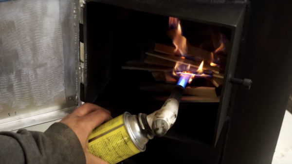
Most of the pieces seem to come from scrap metal lying around the workshop, although the degree to which the entire project comes together is quite smooth. Some filter and spray paint do the trick for cleaning up the furnace and making it look less scrappy. The last step? A stack of wooden logs and a blow torch to start the fun. Outside of the furnace, an LCD screen keeps track of the temperature, giving some feedback and control.
The result is perhaps a too effective at warming up the workshop, but the problem sure is solved!