Learn Shift Registers Without Involving A Microcontroller

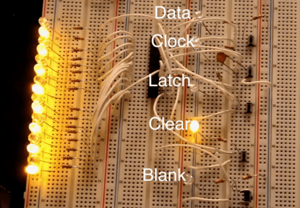
This is a truly hands-on approach to learning. [Kevin Darrah] ditched the microcontroller and is using push buttons to learn about 595 shift registers. The test rig uses two of the serial-in, parallel-out chips. These are cascading which means that as data from the first chip overflows it feeds the input of the second. The parts are commonly used to drive LEDs, or reduce the number of pins needed to drive peripherals like this character LCD.

The five push-buttons give you a chance to intuitively learn how the chip logic works. The blank button is also commonly called Output Enable (OE). Driving it high shuts off the outputs of the chips but doesn’t clear the data. That task is performed by the clear button which is driven low to set all of the shift register memory to zero. The other three buttons set the logic level, shift it into the chip using the clock signal, and push the stored values to the outputs using the latch.

To get a visual approximation of what’s happening inside of these chips you should check out the shift register tutorial linked to in this post.

Continue reading “Learn Shift Registers Without Involving A Microcontroller”

Learn A Little Assembly Language For The 6502 Processor

6502-assembly-tutorial

Evern wanted to write your own Atari 2600 games? This won’t get you quite that far, but it will teach you the very basics. It’s an assembly tutorial for the 6502 processor. The nice thing is that you need nothing more than your browser to participate thanks to the embedded JavaScript emulator which acts as assembler, machine, and debugger in one.

The 6502 was in a lot of early equipment. In addition to the previously mentioned Atari they can be found in the Commodore 64, Apple II, and the original NES. You can even find folks building their own computers around the chip these days (most notable to us is the Veronica project). The guide starts off slowly, providing a working program and challenging the reader to play with to code in order to alter the outcomes. It moves on to an overview of registers and instructions, operators and branching, and culminates in the creation of a simple game.

[Thanks Mathilda]

RPi Video With Pygame

Adafruit has a new tutorial on creating video with an RPi and pygame. The goal is to create custom user interfaces on low cost hardware, powered by the easy to use pygame library. The tutorial walks through getting your RPi set up to run pygame, creating a basic pygame script that controls the framebuffer, and drawing an oscilloscope display on the screen.

This tutorial uses Adafruit’s WebIDE as a development environment. This is an excellent solution for working on video display, since you can develop the code on a networked computer and view the shell while running your graphical application. This is very useful for debugging, since you can just print information to your WebIDE console.

There’s a lot of potential for this setup. It would be ideal for creating any kiosk application. Maybe an announcement display, interactive kiosk, or even a programmable logic controller type user interface? What else could you build with a RPi attached to a LCD touchscreen?

Check out a video of Adafruit’s display in action after the break.

Continue reading “RPi Video With Pygame”

The Inner Workings Of Servo Motors

Servos seem to be the go-to option when adding motors to hobby projects. They’re easy to hack for continuous rotation for use in a robot, but with the control board intact they are fairly accurate for position-based applications. But do you know how the hardware actually works? [Rue Mohr] recently published an article that looks at the inner world of the servo motor.

As you know, these motors use a voltage, ground, and signal connection for control. The position of the horn (the wheel seen on the servos above) is dependent on that control signal. The duty cycle of a 20 ms pulse decides this. Inside the housing is a control board capable of measuring this signal. It’s got a chip that monitors the incoming PWM pulses, but that’s only half of the equation. That controller also needs feedback from the horn to know if its position is correct or needs to be changed. Integrated with the gear box that connects the motor to the horn is a potentiometer. It’s resistance changes as the horn turns. Knowing this, it is possible to fine tune a servo by altering that resistance measurement.

Cheap Spark Detector For Alpha Particles

[JAC_101] wrote in to let us know that the Truely Mad Scientist’s LVL1 Splinter Group just built a simple Alpha Particle detector.  The detector is a high voltage DC spark gap that is triggered by ionizing radiation. Making one of these detectors involves gutting a cold cathode power supply for some high voltage AC, then bumping that source up to crazy high voltage DC with a Cockcroft-Walton generator.  Once the spark gap distance is carefully adjusted it will light up brilliantly with the introduction of a radioactive source, we are told. There are no videos, or even pictures of the thing running, but we found this one that is pretty darn cool. Maybe all that spark-gap related RF killed their camera or something, their page at least promises videos soon.

In the mean time check out Truely Mad Scientist’s LVL1 Splinter Group’s ionizing cloud chamber for more radioactive fun.

Using StellarisWare With The Launchpad

In our last Stellaris how-to we got the board working and set some registers to turn on the LED. This time we’ll start using StellarisWare Driverlib, which provides drivers for the microcontroller’s peripherals including GPIOs, UARTs, ADCs, and so on. These libraries make it easier to control the peripherals. We’ll build the Driverlib project, create a project from scratch to use the library, and run a simple LED blinking example.

Continue reading “Using StellarisWare With The Launchpad”

Getting Started With The Stellaris Launchpad

We’ve already given an overview of the Stellaris Launchpad, but lets look at the first steps to running code on the device. First we’ll get the development software working, then we’ll build and run a very simple example.

TI allows use of the full version of their IDE, Code Composer Studio, with the Launchpad’s on-board debugger. To work with Stellaris microcontrollers, you’ll also need to grab StellarisWare. This free software package contains support for the Stellaris devices including peripheral drivers, a USB library, and code examples. Finally, you’ll need the ICDI drivers to communicate with the debugger. TI has all the required software for this board available here. See the TI getting started directions for a walk-through of how to install the required software.

Continue reading “Getting Started With The Stellaris Launchpad”