As with any other community, it takes all kinds to make the keyboard world go ’round. Some like them thicc — more backing for the clacking and all — but some like them sleek and prefer the slimmest possible keyboard. For now and the foreseeable future, the go-to method for making whisper-thin keebs is to use Kailh Choc switches, because that’s about all that’s out there.
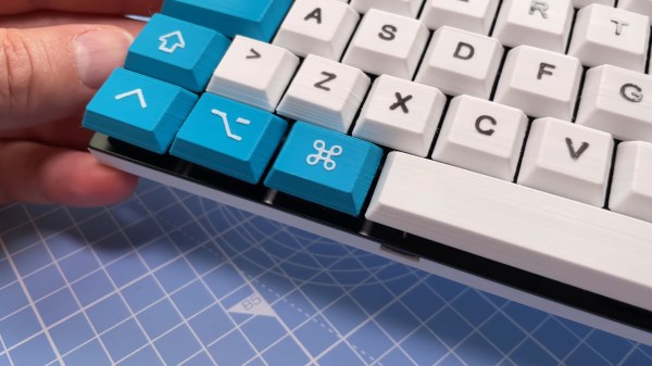
But chocs aren’t for everyone, and there are plenty of die-hard Cherry fans out there that want it both ways. Being one among them, [Khmel] set about designing the lowest-profile possible keyboard (and caps) that uses standard Cherry-sized keyswitches. Shut up and take your money? Well, okay, but the case and keycap files are all available on Thingiverse, so.
The whole video is great, and at less than 2½ minutes long, it’s definitely worth your time. There are a few little gems of wisdom sprinkled throughout, like printing keycaps standing up on their backsides (like where they would have a little flash dot if they were factory-molded). This gives them a nice texture thanks to the layer lines. But the real reason we’re here today is this DIY method for making doubleshot keycaps with little fuss that [Khmel] just tosses out there toward the end.
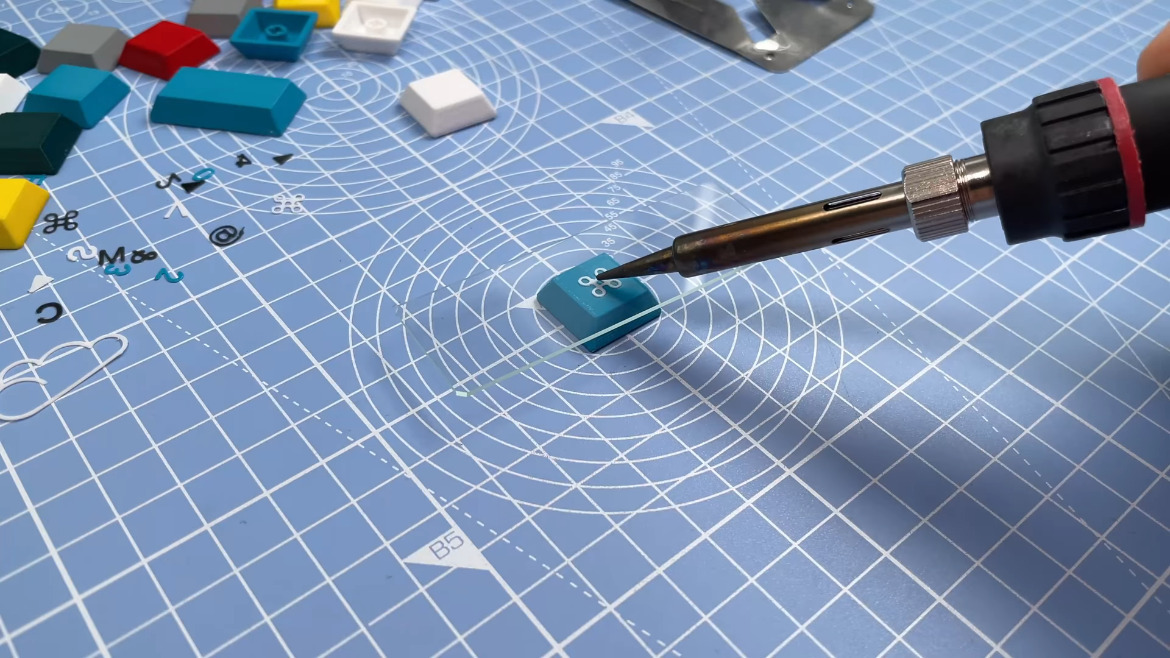
Traditionally, doubleshot keycaps are made with two layers of plastic — one for the legend, and one for the rest. This produces a quite durable keycap and (used to be the norm), but the expensive process gave way to laser-etched and pad-printed keycap legends in the ’90s. [Khmel] was able to fake the look by printing legends at 0.25 layer height and then fusing each one to its respective keycap by laying a thin piece of glass (think microscope slide) on top and applying a soldering iron for a few seconds. Classy!
Tweezing tiny legends not really your kind of tedium? Here’s a method for DIY waterslide decals instead.
Continue reading “Thinnest Keyboard Uses Cherry DIY Doubleshot Method”