Two-Key Keyboard Build Log Starts Small, But Thinks Big

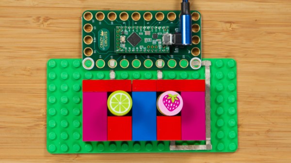
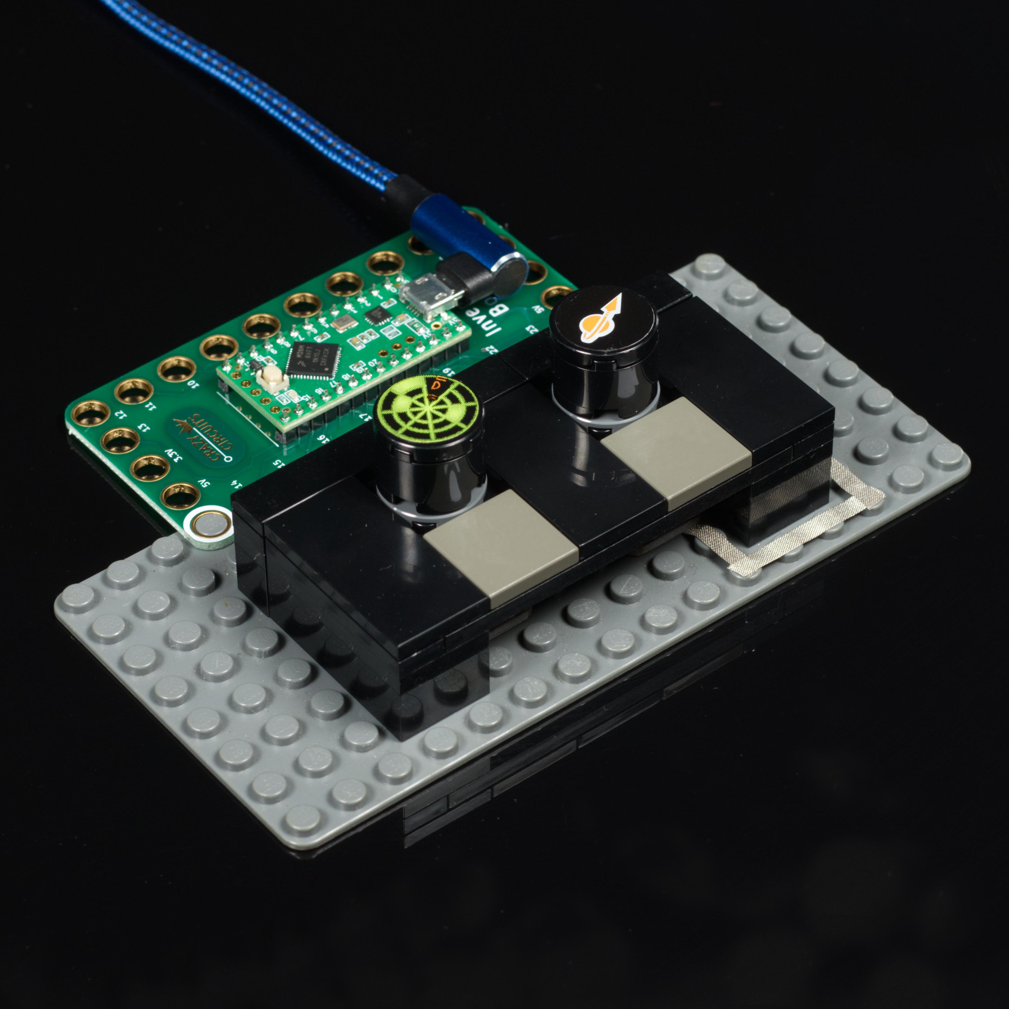
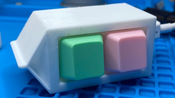
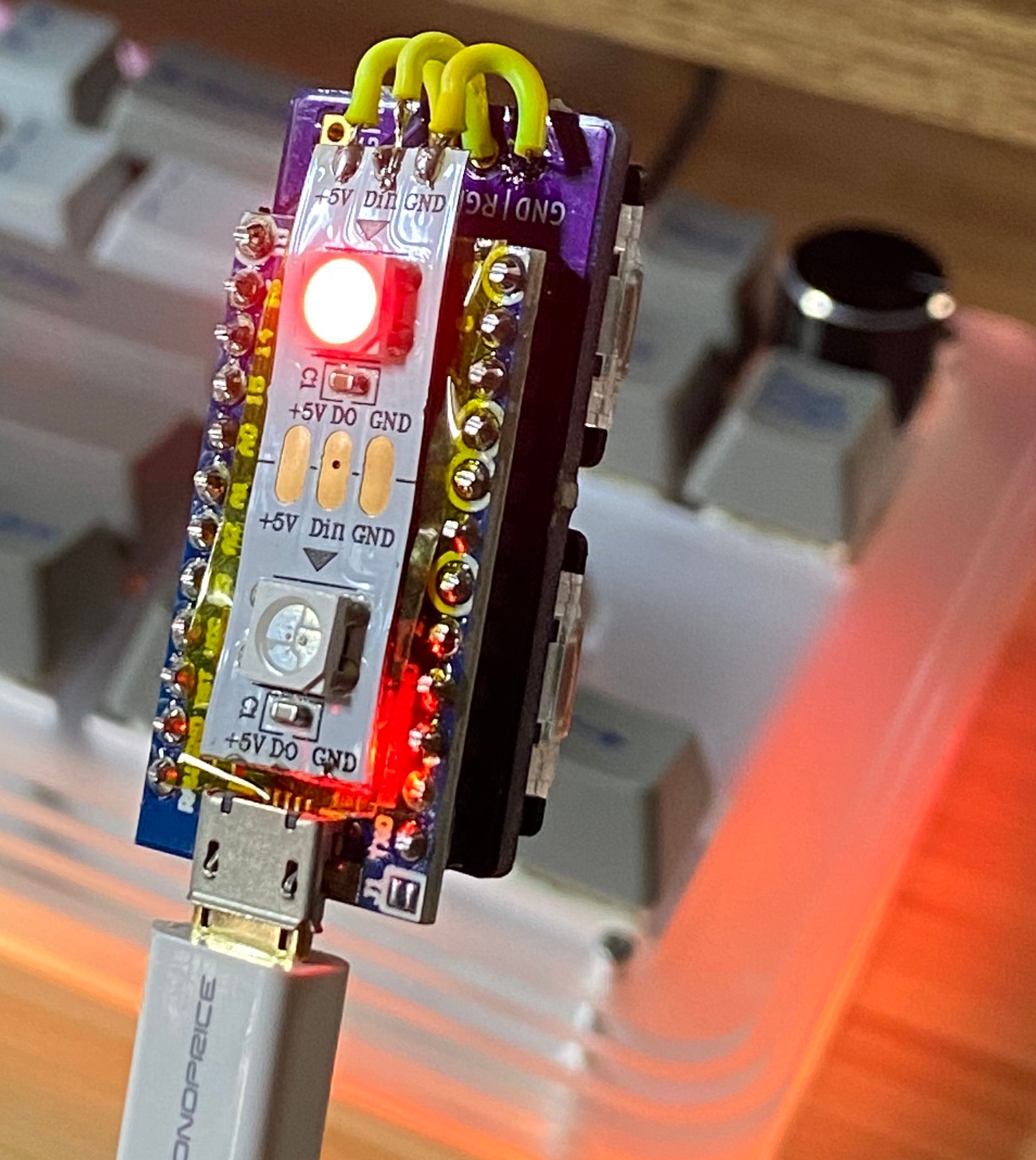
Interested in making a custom keyboard, but unsure where to start? Good news, because [Jared]’s build log for an adorable “2% Milk” two-key mini-keyboard covers everything you need to know about making a custom keyboard, including how to add optional RGB lighting. The only difference is that it gets done in a smaller and cheaper package than jumping directly in with a full-size DIY keyboard.

[Jared] is definitely no stranger to custom keyboard work, but when he saw parts for a two-key “2% Milk” keyboard for sale online, he simply couldn’t resist. Luckily for us, he took plenty of photos and his build log makes an excellent tutorial for anyone who wants to get into custom keyboards by starting small.

The hardware elements are clear by looking at photos, but what about the software? For that, [Jared] uses a Teensy  Pro Micro clone running QMK, an open source project for driving and configuring custom input devices. QMK drives tiny devices like the 2% Milk just as easily as it does larger ones, so following [Jared]’s build log therefore conveys exactly the same familiarity that would be needed to work on a bigger keyboard, which is part of what makes it such a great project to document.

Interested in going a little deeper down the custom keyboard rabbit hole? You can go entirely DIY, but there’s also no need to roll everything from scratch. It’s possible to buy most of the parts and treat the project like a kit, and Hackaday’s own [Kristina Panos] is here to tell you all about what that was like.

Handheld Slayer Exciter Wand Makes For Easy High Voltage Magic

It’s often said that any sufficiently advanced technology is indistinguishable from magic, and when a DIY device lets you light up fluorescent bulbs with a flick of the wrist, it’s certainly not hard to see why. The latest creation from [Jay Bowles], this high voltage wand is actually a Slayer Exciter coil that’s able to boost the output of a standard 9 V alkaline or rechargeable battery high enough to perform some of the wireless power tricks we usually associate with the more complex Tesla coil.

We really can’t overstate how simple it is to build one of these yourself. Sure you’ll still need to wind the coil, but if you can chuck the 1/2 inch acrylic tube into a electric drill you should be able to make short work of it. Once you’ve wound your secondary coil from 32 gauge magnet wire, you only need a couple turns of common doorbell wire to make up the primary.

Think there must be some complex electronics hiding in the handle? Far from it. All that’s hidden by that faux-leather wrapping is a transistor to do the high-speed switching, an LED functioning as both the power indicator and the circuit’s diode, and a resistor. [Jay] put it all together dead bug style, but you could do it on a scrap of perfboard if you’d like something a little more robust.

Being a big believer in STEM education, [Jay] says the wand was designed to be as kid-friendly as possible so he could gift it to his young niece and nephew. Inspiring the next generation is certainly something we respect around these parts, though we think there’s plenty of adults who wouldn’t have been disappointed if they unwrapped a gadget like this over the holidays.

If you’d like to play around with a Slayer but aren’t into the whole Harry Potter motif, you might be interested in the larger and more capable version [Jay] built earlier in the year.

Continue reading “Handheld Slayer Exciter Wand Makes For Easy High Voltage Magic”

ESP8266 Socket Is A Snap-Fit, Breadboard-Friendly Wonder

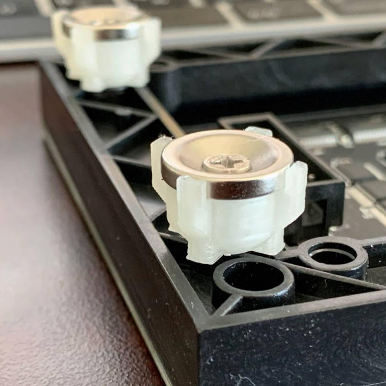
It all started with wanting to program an ESP-12 variant of an ESP8266 module without involving any solder. Displeased with all the socket offerings on Thingiverse, [tweeto] set out to design their own breadboard-friendly snap-fit socket.

This certainly looks like a handy solution. All you have to do is print the thing, add all the wires, and stick your ESP in there. Even that wire is easy to find; [tweeto] used 0.8 mm paper clips which are sturdy, conductive, and haunting the darkest corners of every desk drawer. They’re also a little bit on the thick side, so [tweeto] plans to test out 0.6mm copper wire in the future.

The challenge with this type of print is to design something that will stand up to repeated breadboardings without losing legs or falling apart. [tweeto]’s elegant solution is a tiny groove for each wire in the bottom of the socket — it keeps the wire in place by countering the play caused by inserting it into and removing it from a breadboard. See how [tweeto] bends the paper clips in the short video after the break.

There’s more than one way to use 3D printing to your circuit-building advantage, even in permanent circuits — just take a look at this PCB-free Arduboy.

Continue reading “ESP8266 Socket Is A Snap-Fit, Breadboard-Friendly Wonder”

Knockoff Kapton Nearly Sinks DIY Flex PCB Project

[TinkersProjects] experimented with making their own flexible PCB for LED modules inside a special fixture, and the end result was at least serviceable despite some problems. It does seem as though the issues can be at least partially blamed on some knockoff Kapton tape, which is what [TinkersProjects] used as a backing material.

Incomplete etching on this DIY flexible PCB, but still salvageable.

The approach was simple: after buying some copper foil and wide Kapton tape, simply stick the foil onto the tape and use the toner transfer method to get a PCB pattern onto the copper. From there, the copper gets etched away in a chemical bath and the process is pretty much like any other DIY PCB. However, this is also where things started to go wonky.

Etching was going well, until [TinkersProjects] noticed that the copper was lifting away from the Kapton tape. Aborting the etching process left a messy board, but it was salvageable. But another problem was discovered during soldering, as the Kapton tape layer deformed from the heat, as if it were a piece of heat shrink. This really shouldn’t happen, and [TinkersProjects] began to suspect that the “Kapton” tape was a knockoff. Switching to known-good tape was an improvement, but the adhesive left a bit to be desired because traces could lift easily. Still, in the end the DIY flexible PCB worked, though the process had mixed results at best.

Flexible PCBs have been the backbone of nifty projects like this self-actuating PoV display, so it’s no surprise that a variety of DIY PCB methods are getting applied to it.

Heat Turns 3D Printer Filament Into Springs

The next time you find yourself in need of some large-ish plastic springs, maybe consider [PattysLab]’s method for making plastic springs out of spare filament. The basic process is simple: tightly wind some 3D printer filament around a steel rod, secure it and wrap it in kapton tape, then heat it up. After cooling, one is left with a reasonably functional spring, apparently with all the advantages of annealed plastic.

The basic process may be simple, but [PattysLab] has a number of tips for getting best results. The first is to use a 3D-printed fixture to help anchor one end of filament to the steel rod, then use the help of an electric drill to wind the filament tightly. After wrapping the plastic with kapton tape (wrap counter to the direction of the spring winding, so that peeling the tape later doesn’t pull the spring apart), he suspends it in a pre-heated oven at 120 C for PLA and 160 C for PETG. How long does it stay in there? [PattysLab] uses the following method: when the spring is wound, he leaves a couple inches of filament sticking out to act as a visual indicator. When this segment of filament sags down, that’s his cue to begin the retrieval process. After cooling, the result is a compression or extension spring, depending on how it was wound before being heated.

[PattysLab] shared a short video on this Reddit post that shows both springs in action, and the process is all covered in the video, embedded below.

Continue reading “Heat Turns 3D Printer Filament Into Springs”

Dog Bowls Show The Versatility Of Ceramic Slip Casting

Here at Hackaday, we feature projects that are built of just about every material imaginable. Silicon-spangled fiber-reinforced epoxy resin is our primary medium, but we see plastic, wood, steel, aluminum, and even textiles from time to time. It’s not often we see slip-cast ceramic molding, though, and when it pops up, it’s always good to take a look at this versatile manufacturing method.

The back-story on this one is that [thoughtfulocean], a mechanical engineer idled by COVID lockdowns, wanted custom water bowls for his dogs, one of whom is clearly a grumpy Ewok. The design started with a 3D-print of the final vessel, printed in sections and glued together. These were used to create a two-piece plaster mold into which a watery slurry of clay, or slip, was poured. The plaster mold dehydrates the slip, leaving behind a semi-solid layer of clay of the desired thickness once the excess slip is poured off. The resulting casting is then fired in a kiln and glazed.

Of course, [thoughtfulocean] ran into a few problems along the way. The first mold was warped thanks to the mold box bowing under pressure from the plaster, so the whole molding process had to be revamped. The finished bowl also shrunk less than expected after firing, which led to some more revisions. But the finished bowl look really nice, and the included pump and filter keeps the Ewok’s water free from the yuck a dog’s face can introduce. As a bonus, it sounds like [thoughtfulocean] might have created a marketable product from all this. Take that, COVID!

Slip-casting ceramic may not be all that common around here, but ceramic as a material isn’t exactly a stranger. And who says slip casting is limited to ceramic? After all, we’ve seen a similar method used with plastic resin.

[via r/engineering]

Remoticon Video: The Mechanics Of Finite Element Analysis

Hardware hacking can be extremely multidisciplinary. If you only know bits and bytes, but not solder and electrons, you’re limited in what you can build. The same is true for mechanical design, where the forces of stress and strain suddenly apply to your project and the pile of code and PCBs comes crashing to the ground.

In the first half of his workshop, Naman Pushp walks you through some of the important first concepts in mechanical engineering — how to think about the forces in the world that act on physical objects. And he brings along a great range of home-built Jugaad props that include a gravity-defying tensegrity string sculpture and some fancy origami that help hammer the topics home.

In the second half of the workshop, Naman takes these concepts into computer simulation, and gives us good insight into the way that finite-element analysis simulation packages model these same forces on tiny chunks of your project’s geometry to see if it’ll hold up under real world load. The software he uses isn’t free by any definition — it’s not even cheap unless you have a student license — but it’s nonetheless illuminating to watch him work through the flow of roughly designing an object, putting simulated stresses and strains on it, and interpreting the results. If you’ve never used FEA tools before, or are looking for a compressed introduction to first-semester mechanical engineering, this talk might be right up your alley. Continue reading “Remoticon Video: The Mechanics Of Finite Element Analysis”