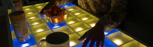
Some hackers make functional things that you can’t allow to be seen in polite company. Others make beautiful things that could come from a high-end store. [Marija] falls into the second category and her interactive LED coffee table would probably fetch quite a bit on the retail market. You can see a video of the awesome-looking table, below.
It isn’t just the glass, MDF, and pine construction. There’s also a Bluetooth interface to a custom Android application from [Dejan], who collaborated on the project. However, if you aren’t comfortable with the woodworking, [Marija’s] instructions are very detailed with great pictures so this might be a good starter project.
It wouldn’t be much of a stretch to say that here at Hackaday, we’re about as geeky as they come. Having said that, even we were surprised to hear that there are people out there who collect elements. Far be it from us to knock how anyone else wishes to fill their days, but telling somebody at a party that you collect chemical elements is like one step up from saying you’ve got a mold and fungus collection at home. Even then, at least a completed mold and fungus collection won’t be radioactive.
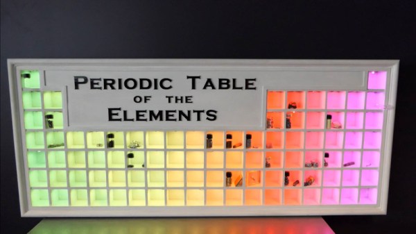
But if you’re going to spend your spare time working on a nerdy and potentially deadly collection, you might as well put it into an appropriate display case. You can’t just leave your Polonium sitting around on the kitchen counter. That’s the idea behind the interactive periodic table built by [Maclsk], and we’ve got to admit, if we get to put it in a case this awesome we might have to start our own collection.
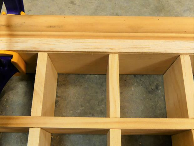
A large portion of this project is building the wooden display case itself as, strangely enough, IKEA doesn’t currently stock a shelving unit that’s in the shape of the periodic table. The individual cells and edge molding are made of pine, the back panel is MDF, and the front of the display is faced off with thin strips of balsa to cover up all the joints. Holes were then drilled into the back of each cell for the LED wiring, and finally the entire frame was painted white.
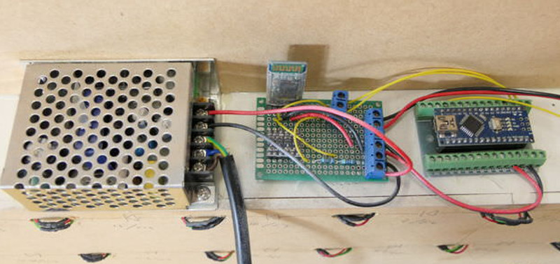
Each cell contains an WS2812B RGB LED, which at maximum brightness draws 60mA. Given the 90 cells of the display case, [Maclsk] calculated a 5.4A power supply would be needed to keep everything lit up. However, he found a 4A power supply that made his budget happier, which he reasons will be fine as long as he doesn’t try to crank every cell up to maximum at the same time. Control for the display is provided by an Arduino Nano and HC05 Bluetooth module.
The final piece of the project was the Android application that allows the user to control the lighting. But it doesn’t just change colors and brightness, it’s actually a way to visualize information about the elements themselves. The user can do things like highlight certain groups of elements (say, only the radioactive ones), or light up individual cells in order of the year each element was discovered. Some of the information visualizations are demonstrated in the video below, and honestly, we’ve seen museum displays that weren’t this well done.
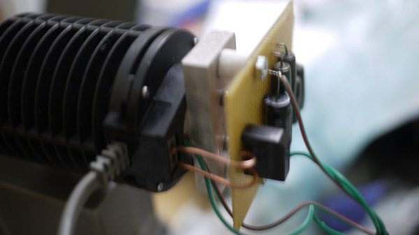
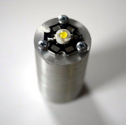
[Amen] obtained a microscope whose light source was an incandescent bulb, but the light from it seemed awfully dim even at its brightest setting. Rather than hunt down a replacement, he decided to replace the bulb with a 1W LED mounted on a metal cylinder. The retrofit was successful, but there were numerous constraints on his work that complicated things. The original bulb and the LED replacement differed not just in shape and size, but also in electrical requirements. The bulb was also part of an assembly that used a two-pronged plug off to the side for power. In the end, [Amen] used 3D printing, a bit of metal work, and a bridge rectifier on some stripboard to successfully replace his microscope’s incandescent bulb assembly with an LED. He even used a lathe to make connector pins that mated properly with the microscope’s proprietary power connector, so that the LED unit could be a drop-in module.
Working on existing equipment always puts constraints on one’s work, usually due to space limitations, but sometimes also proprietary signals. For example, a common issue when refitting a projector with an LED is to discover that the projector expects a stock bulb, and refuses to boot up without one. Happily, the microscope didn’t care much about the bulb itself, and with the LED positioned in roughly the same position as the original bulb’s filament [Amen] obtained smooth and even lighting across the field of view with no changes made to the microscope itself.
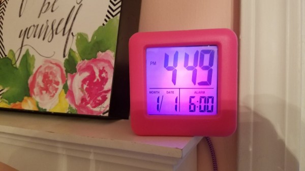
Hackaday reader [Don] dropped by the tip line recently to let us know about the latest version of his color-changing LCD clock project. This is his second version of the hardware which makes some pretty big improvements over the original, including moving from the Pi B to the Pi Zero and an internal simplification of the wiring. He mentions the next revision of the project will focus on Google Home integration, which should be interesting to see.
As a father of two pre-school age children, he was looking for a way to help his kids understand the concept of time and scheduled activities. Colors and shapes come fairly easy to children of this age, but time and how it relates to the day is a bit more difficult for them especially as their comprehension of numbers is still developing. [Don] reasoned that even if they couldn’t read the numbers on the clock yet, if he had the display change colors to indicate different periods of the day (sleep, play, cleanup, etc), it would not only keep them on schedule, but reinforce the meaning of the numbers on the screen.
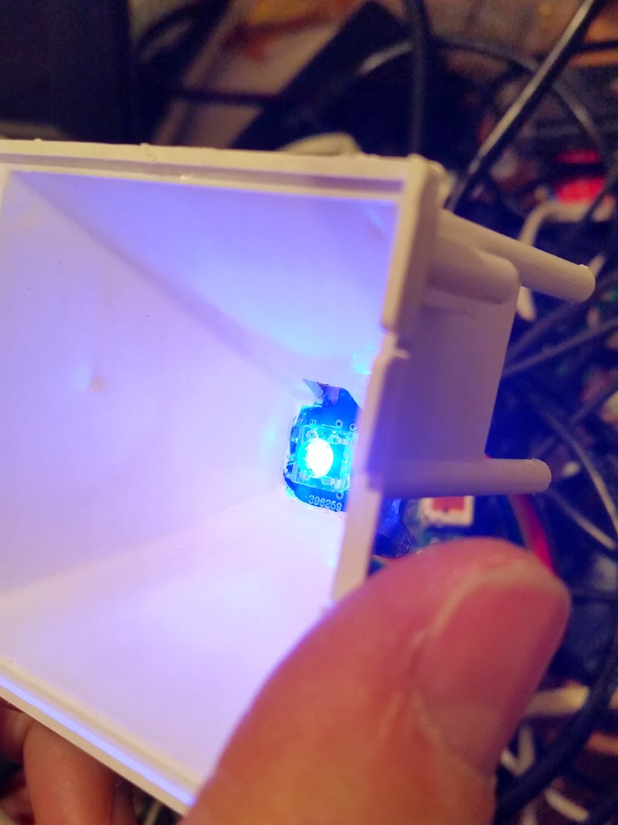
ShiftBrite installed in the projector.
The project was made infinitely easier by a lucky find at a local retailer. For $10 he got a kid-friendly looking clock that utilized a simple projector to backlight the LCD display. This meant [Don] would just need to swap out the stock lighting module for a controllable RGB LED, and the hardware modifications would essentially be complete.
Even the Pi Zero fits perfectly inside the case of the clock, the only modification necessary was cutting a little hole in the back for the Pi’s micro USB port. His earlier version used an external Pi B connected to the clock via CAT5, so getting it all integrated into the one device is a huge improvement, especially when little kids are involved. Moving the Pi and its 5 V pins into the clock itself also allowed [Don] to drop the voltage regulator required previously.
With the basic hardware for a color changing LCD clock together, the rest of the project was just a matter of software. After some research, [Don] came across RPi-ShiftBrite by [Hive13] and made his own fork which added some features necessary for his project, namely the ability to quickly set the ShiftBrite to a specific color on the command line. To schedule the color changes, he used the very slick minicron: a web-based tool to create and monitor Linux cron jobs.
The Pi itself does not actually interface with the clock, and with no onboard RTC it’s necessary to keep it updated with NTP or else the times will become desynchronized. It can be necessary to sync the Pi’s clock to the Internet as often as every hour to make sure the colors shift at the appropriate times. The addition of a RTC module like the DS1307 could alleviate this issue and might be something to consider for a future revision.
All told, a fantastic project and something we’ll be sure to keep our eyes on as it progresses. We’ve seen our share of unique Raspberry Pi powered clocks, and even a few color changing ones, but this approach is easily the most straight-forward we’ve seen.
[Modustrial Maker] is at it again with another seriously cool LED visualizer. This time around, he’s built pair of pendant lights inspired by the rings of Saturn.
The rings are made mostly of walnut plywood using a circle router jig to make the cut easier. If you are inspired to make these for yourself, [Modustrial Maker] is clear — the order in which you cut out the pieces of the rings is absolutely critical. The pieces are glued together — with any edges sanded smooth — and edgebanding applied using a hot air gun due to the curved surface before staining. Duplicate for the second (or more if you so choose!) rings. Be forewarned — a little geometry will be needed to find anchor points that will keep the rings properly balanced.
[Modustrial Maker] suggests an off-the shelf LED controller to handle the visualizations and lighting effects, but he used an Arduino Mega clone as the brains — code available here, a MonkeyJack MAX9814 electret mic, and a four-channel RF remote/transceiver to control the different modes. Pulsing along to the music, these rings make for sleek lighting indeed.
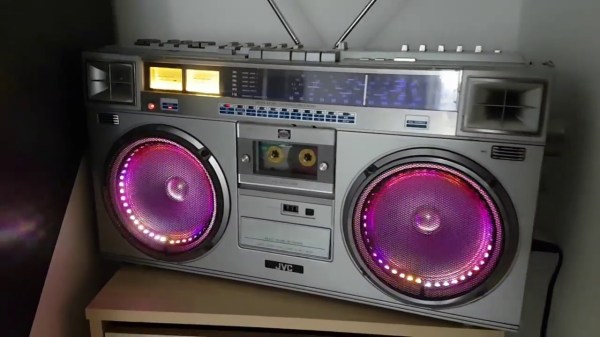
Old boomboxes make great hacks. Their design is iconic; yes they look dated but that really just builds on the nostalgic urge to have one hanging around. Plus their big cases simply invite adding things inside in a way impossible with contemporary electronics.
[Danc0rp] hacked his JVC M70 boombox to make the speakers glow with animated light, bumping VU meters, and a pulsing horizontal bar above the tape deck. The effect is superb. The cones of the speakers act like a projection surface and the grilles hide the LEDs until they activate, and enhance the effects once unleashed. It is one of the best LED speaker hacks we’ve ever seen.
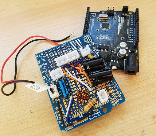
Custom board with Arduino UNO
The light effects are provided by LED strips, which for the speakers are attached just inside the outer rim. The brains behind it all is an Arduino UNO. To connect to it, he soldered components to a blank Arduino prototyping board. That board takes input from the boombox’s line-out and does some filtering (an attempt to address some ground noise) before passing the signal on to the Arduino. That board also interfaces between the Arduino and the LED strips. The schematic is available on his GitHub page. He’d like to replace the board with a custom PCB instead and is looking for design help.
The result is not only beautiful but professional looking too. This makes us wonder why boomboxes don’t come this way. See it for yourself in the video below.
 [Amen] obtained a microscope whose light source was an incandescent bulb, but the light from it seemed awfully dim even at its brightest setting. Rather than hunt down a replacement, he decided to