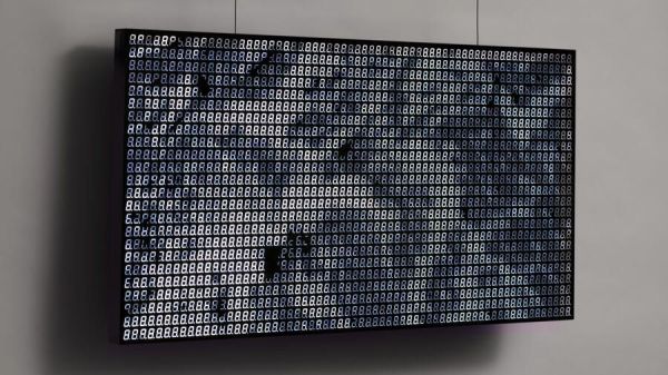
We’re not sure, but the number of recognizable alphanumeric characters that a seven-segment display can manage seems to have more to do with human pattern recognition than engineering. It takes some imagination, and perhaps a little squinting, to discern some characters, though. Arguably better is the fourteen-segment display, which has been pressed into service in this just-for-funsies IOT message board.
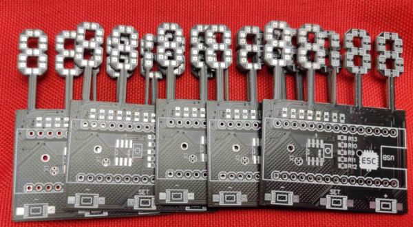
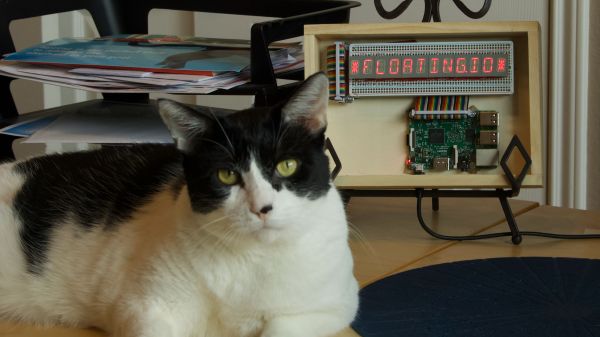
 As [Steve] tells the story, this is one of those “boredom-buster” projects that start with a look through the junk bin to see what presents itself. In his case, some fourteen-segment common-cathode LEDs presented themselves, and the result was a simple but fun build. [Steve] used some clever methods to get the display stuffed onto two protoboards, including mounting the current-limiting resistors cordwood-style between the boards. A Raspberry Pi drives the display through a very neatly routed ribbon cable, and the whole thing lives in a tidy wooden box.
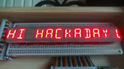
The IOT part of the build allows the display to show messages entered on [Steve]’s web page, with a webcam live stream to close the loop. Strangely, the display seems stuck on the “HI HACKADAY!” we entered as a test after [Steve] tipped us off, so we’re not sure if we busted it or what. Apologies if we did, [Steve]. And by the way, if your cats are named [Nibble] and [Pixel], well done!
No matter what you do with them, multi-segment displays are pretty cool. But if you think they’re something new, you’ve got another think coming.