Let’s face it, synthesizers are awesome. But commercial synths are pretty expensive. Even the little toy ones like the KORG Volca and the MicroKORG will run you a few hundred bucks. For the most part, they’re worth the price because they’re packed with features. This is great for experienced synth wizards, but can be intimidating to those who just want to make some bleeps and bloops.
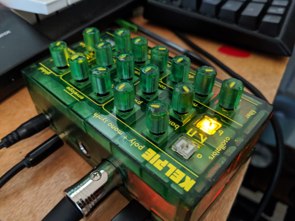
[Kenneth] caught the mini-synth bug, but can’t afford to catch ’em all. After a visit to the Moog factory, he was inspired to engineer his own box based on the Moog Sirin. The result is KELPIE, an extremely portable and capable synth with 12 voices, 16 knobs, and 4 LED buttons. KELPIE is plug and play—power and a MIDI device, like a keyboard, are the only requirements. It has both 1/8″ and 1/4″ jacks in addition to a standard MIDI DIN connection. [Kenneth] rolled his own board based on the Teensy 3.2 chip and the Teensy audio shield.
Part of the reason Kenneth built this synthesizer is to practice designing a product from the ground up. Throughout the process, he has tried to keep both the production line and the DIYer in mind: the prototype is a two-part resin print, but the design could also be injection molded.
We love that KELPIE takes its visual design cues from the translucent candy-colored Game Boys of the late 90s. (We had the purple one, but always lusted after the see-through kind.) Can we talk about those knobs? Those are resin-printed, too. To color the indicators, [Kenneth] used the crayon technique, which amounts to dripping molten crayon into the groove and scraping it off once hardened. Don’t delay; glide past the break to watch a demo.
Continue reading “Candy-Colored Synth Sounds Sweet” →
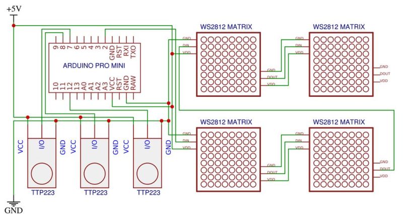


 This time-honored method of using very few I/O pins to control many LEDs makes it possible to control 72 LEDs without dedicating 72 pins. The density makes animations look stunning and the digital nature melts away leaving a distinct analog charm.