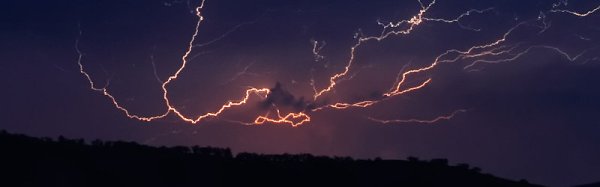
Lightning storm detectors have been around for a surprisingly long time. The early designs consisted of a pair of metal bells and a pendulum. When there was a charge applied, for example by connecting one bell to the ground and the other to a lightning rod, the bells would ring when a lightning storm was close by. In the mid 18th century, these devices were only practical for demonstration and research purposes, but very likely represent the earliest devices that convert electrostatic charge to mechanical force. A bit over a hundred years later, the first lightning detector was considered by some as the first radio receiver as well.
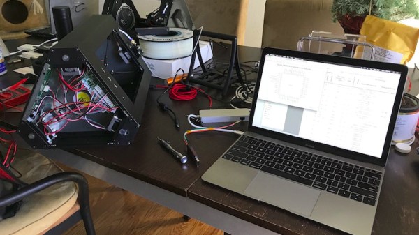
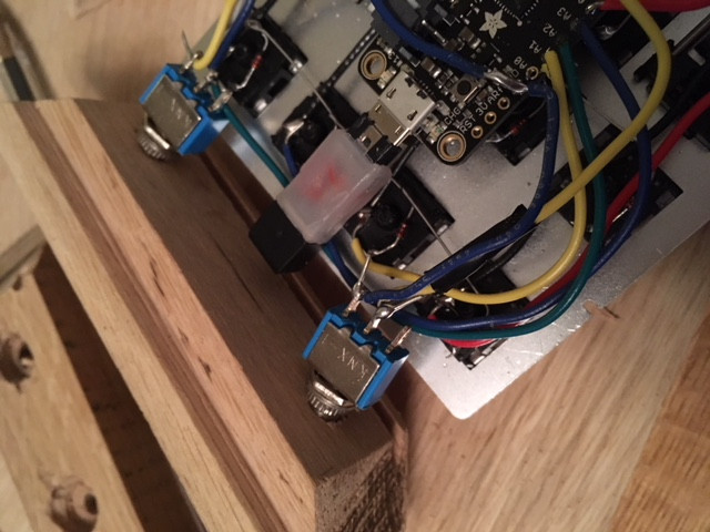
As soon as I found out about storm detector chips, I knew I would have to get one working. For about $25, I ordered an AMS AS3935 module from China. This chip has been featured before in a number of excellent projects such as Twittering lightning detectors, and networks of Sub-Saharan weather stations. While there’s an Arduino library for interfacing with this IC, I’m going to be connecting it up to an ESP8266 running the NodeMCU firware, which means digging into the datasheet and writing some SPI code. If any of the above tickles your fancy, read on! Continue reading “An Introduction To Storm Detector Modules”