Prototyping With The ATMega1284P

While most people are moving onto ARMs and other high-spec microcontrollers, [Dave Cheney] is bucking the trend. Don’t worry, it’s for a good reason – he’s continuing work on one of those vintage CPU/microcontroller mashups that implement an entire vintage system in two chips.

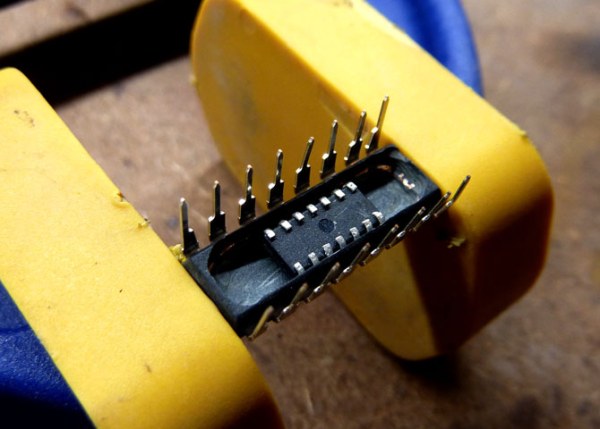
While toying around with the project, he found the microcontroller he was using, the ATMega1284p, was actually pretty cool. It has eight times the RAM as the ever-popular 328p, and twice as much RAM as the ATMega2560p found in the Arduino Mega. With 128k of Flash, 4k of EEPROM, 32 IOs, and eight analog inputs, it really starts to look like the chip the Arduino should have been built around. Of course historical choices don’t matter, because [Dave] can just make his own 1284p prototyping board.

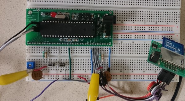
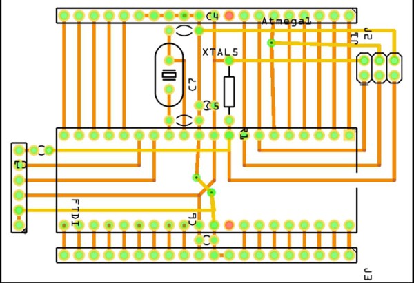
The board is laid out in Fritzing with just a few parts including a crystal, a few caps, an ISP connector, and pins for a serial connector. Not much, but that’s all you need for a prototyping board.

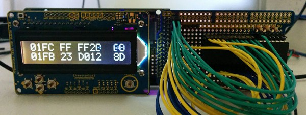
The bootloader is handled by [Maniacbug]’s Mighty 1284 Arduino Support Package. This only supports Arduino 1.0, not the newer 1.5 versions, but now [Dave] has a great little prototyping board that can be put together from perfboard and bare components in a few hours. It’s also a great tool to continue the development of [Dave]’s Apple I replica.

A Dev Board For The ESP Lua Interpreter

From the great minds behind the NodeMCU Lua interpreter for the ESP8266 comes a proper dev board for the WiFi platform of 2015. They are calling it, the NodeMCU-devkit, and it’s a reasonable, cheap, and breadboardable breakout board for the ESP8266.

The version of ESP8266 used in this project is the ESP-12, the newer, fancier model with RF shielding, a questionable FCC logo, and every single one of the GPIOs exposed on castellated connectors. The rest of the board is a USB to serial converter (the CH340G – probably the cheapest USB to serial chip out there), a few passives, and a USB micro connector. It’s simple, cheap, and open source. You can’t do better than that.

This dev board is explicitly designed to work with the NodeMCU firmware, a Lua-based firmware for the ESP. Already we’ve seen some projects make the Hackaday front page with this firmware. Sure, it’s just a garage door opener, but that’s extremely impressive for a chip that’s only a few months old.

Thanks [Baboon] for the tip.

Robotically-Tuned Tube Radio

Dubbed the “Robot Radio” by [Brek], this clinking-&-clunking project merges three generations of hackers’ favorite technologies: robots, vacuum tubes, and microcontrollers. After the human inputs the desired radio frequency the machine chisels its way through the spectrum, trying its best to stay on target.

This build began its life as a junky old tube radio that [Brek] pulled out of a shed. The case was restored and then the hacking began. Inserted between the human and the radio, a PIC 16F628A keeps watch in both directions. On one side, the radio’s tank circuit is monitored to see what frequency the radio is currently playing. On the other, the human’s input sets a desired frequency. If the two do not match, the PIC tells a stepper motor to begin cranking a pair of gears until they do.

Another interesting feature is that as the tubes and other electronics warm up and change their values, the matching circuit will keep them in line. [Brek] shows this in the video by deliberately sabotaging the gears and seeing the robot adjust them back where they belong.

As an afterthought, the Robot Radio was supplemented with a module that adds 100khz to the signal so that the information from a nearby airport can be received.

[Brek] styled the whole machine up with some copper framing and other bits, similar to his spectacular atomic clock build we featured last month.

See the video of the radio tuning after the break.

Continue reading “Robotically-Tuned Tube Radio”

Weird Clocks And A Two Chip Apple I

The Apple I, [Woz]’s original, had about sixty chips on a single board. Most of these chips were logic glue or hilariously ancient DRAMs. The real work was done by the 6502, the 6821 PIA, and the Signetics video chip. It’s a simple computer, really, and following the now popular tradition of two-chip computers, [Dave] built a replica of the Apple I using a 6502 and an ATMega.

The ATMega in this project takes care of everything – the 4k of RAM, the few bytes of ROM, the IO, and even the clock. With the 6502 you can have a little bit of fun with the clock; because the 6502 reads data off the bus a few nanoseconds off the falling edge of the clock and writes on the rising edge, [Dave] played around with the duty cycle of the clock to give the ATMega a bit more time to do its thing. With a 50% duty cycle, the 16Mhz ‘Mega has about eight cycles to decode an address and read or write some data. By making the low part of a clock cycle longer, he has about 45 cycles on the ‘Mega to do all the work. All of this was inspired by a fantastic tutorial on the 6502 clock.

Right now [Dave] has some hex values displaying on a small LCD, while the real I/O is handled by a serial connection to a computer. It’s retro enough, and a future update will include a faux cassette interface, possibly using an SD card for storage.

Student Trolls Anti-Arduino Prof With Parasite MCU

Like some of our grouchier readers, [PodeCoet]’s Digital Sub-Systems professor loathes everyone strapping an Arduino onto a project when something less powerful and ten times as complicated will do. One student asked if they could just replace the whole breadboarded “up counter” circuit mess with an Arduino, but, since the class is centered around basic logic gates the prof shot him down. Undeterred, our troll smuggled an MCU into a chip and used it to spell out crude messages.

No Arduino? No problem. It took him 4 tries but [PodeCoet] hollowed out the SN74LS47N display driver from the required circuit and made it the puppet of a PIC16F1503 controller. The PIC emulated the driver chip in every way – as ordered it showed the count up and down – except when left unattended for 15 seconds. Then instead of digits the PIC writes out “HELLO”, followed by three things normally covered by swimsuits and lastly a bodily function.

For such a simple hack it is wonderfully and humorously documented. There are annotated progress/failure pictures and video of the hack working.

It is not as elaborate as the microscopic deception in the infamously impossible 3 LED circuit, but it gets to the point sooner.

Continue reading “Student Trolls Anti-Arduino Prof With Parasite MCU”

8-Bit Chip Rocks 16-Bit 44.1kHz Tunes

There’s a special place in our hearts for chip tunes generated with your favorite microcontroller. But why stop there? Full-featured audio is a great challenge and it’s not often we see examples of this caliber. It puts out CD-quality audio using not much more than a microcontroller.

How do you get 16-bit audio out of an 8-bit microcontroller. We’ll give you a hint: two pins are used. Not helping? Here it comes: two 8-bit DACs PWM outputs are used on this chip, the ATmega1284. One is used for the lower eight bits, the other handles the upper. The two are combined using carefully calculated precision resistor values and the results are beyond what you imagine. This is produced at a bitrate of 44077.135, slightly off from the 44100Hz standard but we challenge you audiophiles to tell the difference. The wave files are served from an SD card read by the chip using the Petit-FatFs library.

There are so many great things about this project. First off, following [Wancheng Zhou’s] example will let anyone with even basic microcontroller skills build a digital audio player for an [Andrew Jackson] and a couple of [Washingtons]. Secondly, those with a medium uC skill level will want to take the idea and implement/debug it for themselves. Bringing it home, [Wancheng] shows how to gauge the quality of the audio output using FFT.

If you didn’t figure it out by the time of year, this is yet another example of a Cornell ECE 4760 final project. Shout out to [Bruce Land] for inspiring awesome projects and requiring extensive documentation of the projects which itself promotes deeper understand all around.

Continue reading “8-Bit Chip Rocks 16-Bit 44.1kHz Tunes”

Smart CPR Dummy

Smart CPR Dummy Makes Sure You Do It Right

Have you ever taken a First Aid & CPR training course? Don’t you just love the realism of the dummy mannequins you get to practice on? [Park, Qurashi, & Chen], who are students of Cornell University, thought the dummies could use an intelligent upgrade.

It’s the final project for their electrical and computer engineering course ECE 4760. And what they’ve done is successfully created a budget friendly CPR not-so-dumb dummy using the venerable ATmega1284 microcontroller.

The dummy can sense when chest compressions are given, if the nose is plugged properly when breaths are given, if the head is tilted back properly to open the airway, and it even makes use of a microphone to detect if breaths are given properly! While it does this, it uses LED eyes and an LCD screen to provide training feedback to the student. Once the students are sufficiently practiced, it also has a “real” mode that doesn’t give you any feedback to make sure the students truly learned the technique. Continue reading “Smart CPR Dummy Makes Sure You Do It Right”