Gold Leaf Circuit Board

Ah, the glitter of gold… or fake gold, we’re not really sure. But [Mike Hogan] and [PJ Santoro] have been working with faux gold leaf as a conductor on circuit boards. The device you see above is mounted on metal-covered paper substrate and it really works.

They started by applying spray adhesive to heavy paper to make the gold-clad they needed. This was cut down into hexagons in homage to their hackerspace, Hive76 in Philadelphia. From there the shape of the microcontroller (an MSP430 G2211 in this case) to prevent shorts under the chip. The leads were flattened to interface well with the gold contacts, and a hobby knife was used to score the traces. Some careful soldering made up the final connections, and they were in business.

Oh, wait; chip on board but nothing on chip. They forgot to program it first! Since there’s no header they needed an easy way to interface with the board. The clever guys used the power of magnets to hold alligator clips in place. See how they did that in the demo video after the break.

They’re also working on some boards that use conductive ink similar to this hack but we haven’t seen a write-up from these two about those experiments… yet.

Continue reading “Gold Leaf Circuit Board”

Puncher Tracks Your Freelancing Hours, Time Spent In TSA Patdowns

freelance-puncher

[Raphael Abrams] does a lot of freelance work, but he has trouble accurately keeping track of the hours he has put in for his clients. After trying various applications and methods of logging his time, he finally decided to build a device that worked just the way he liked.

He calls his device the “Freelance Puncher”, though it already has been nicknamed the detonator, as it looks like something you would find in the hands of a [James Bond] villain. The device uses a PIC16LF1827 to track the time, saving his logged hours to the built-in EEPROM when powered off. A pair of 7-segment displays are used to display the accumulated hours upon power-on, and a set of seven SMT LEDs separated into two banks keep track of quarter and hundreds of hours worked.

[Raphael] has made his code and schematics available on Github, so you can easily replicate his work if you are looking for a better way to track your time. We think it looks great, though it could be the sort of thing that traveling freelancers might want to keep in their checked luggage, unless they want to spend some quality time with the TSA! Be sure to stick around to see a short video where [Raphael] shows off and explains how his Freelance Puncher works.

Continue reading “Puncher Tracks Your Freelancing Hours, Time Spent In TSA Patdowns”

JTAG Dongle Pushes Code To FPGA After Bootup

This gnarly beast has near-magical qualities. [Sprite_TM] patched it together as a dongle which attaches to a JTAG header (we’re fairly certain this is not a standard footprint for that interface though). He uses it to push code to an FPGA after that device boots. Why? Well, there’s several reason, but the most generic answer is that some boards will not boot unless there is a chain of trust that validates the code which will be running.

In this case, [Sprite_TM] is using a knock-off board he acquired from a Chinese supplier. It’s a hardware network terminal (thin client), and as you can see in the video after the break, it works just fine. But that’s pretty boring and he wanted to use it for his own purposes. When he plugs in the dongle and powers up the board the network terminal is nowhere to be found, replaced with the code to play Pac-Man as if were a full arcade cabinet.

The dongle is simply a female DIL header, an ATtiny85, and a flash memory chip. The AVR has a software UART that speaks XSVF, the protocol used to push data to the FPGA. The data to be written is stored in the memory chip, and with that header in place reprogramming the AVR is just a matter of connecting an ISP programmer. Brilliant!

Continue reading “JTAG Dongle Pushes Code To FPGA After Bootup”

Using A Cheap Accelerometer With Arduino Comes With A Catch

[Boris Landoni] put together a guide to using an inexpensive 3-axis accelerometer with Arduino. The chip that he chose for the exercise is an MMA7455L made by Freescale. It’s got a lot of nice features packed into it, using hardware to do some of the things you’d need software for with other chips like reporting in which direction the chip is moving, detecting when movement has stopped, and few others. It’s an I2C device, so the examples he provides will be super simple to port to your uC of choice.

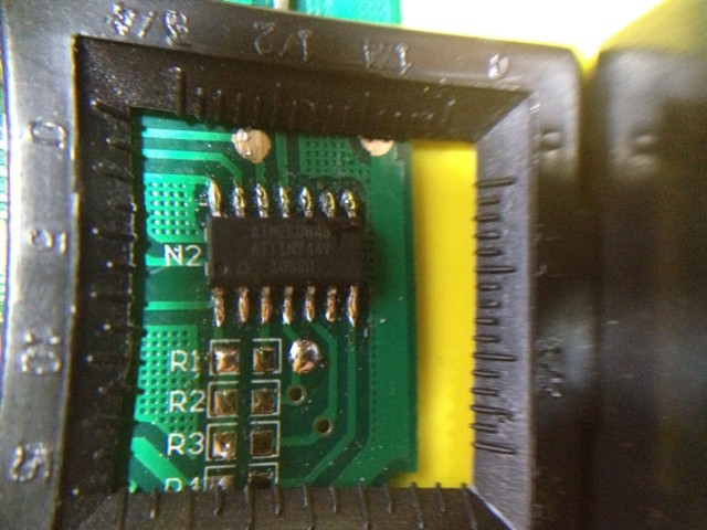
But as the title says, there’s a catch. The chip is extremely versatile and you can get your hands on one for under $2. But check out the size of it. That’s a DFN (dual flat no-lead) package which means there are no pins on it. The package has solder contacts on the bottom which do not protrude out the sides. If you want to do some at-home prototyping with the chip you’ll need a hot air pencil or reflow gear as hand soldering is unlikely to be successful. We’re not saying it’s impossible, but it is quite tricky.

Of course, if you’ve got the secret to getting this done with a quality soldering iron we’d like to hear about it.

ultimate-breadboard

The Ultimate Breadboard – A Prototyping Station That Has It All

[Claudio] was working on a homebrew oscilloscope project when he started thinking about how unsuitable a standard breadboard is for a large-scale project. Rather than adding components on top of components until they became what he lovingly calls a “fragile, unforgiving crapstack”, he decided to build himself the Ultimate Breadboard.

He packed so much into his design, that it’s honestly hard to know where to begin describing it. Aside from an appropriately large breadboarding surface embedded in the center of the console, he added a power supply to the left hand side, which sits just below an Avr-Net-IO board. The right side of the console features an Arduino NG, and a pair of level converters. He also added some LED-based VU meters, a couple of 7-segment displays, an LCD display, an analog voltmeter, along with plenty of I/O connectors.

The Ultimate Breadboard might look a bit daunting at first, but it seems like an awesome setup on which to do any sort of prototyping. Be sure to check out the video below for more details and to see [Claudio] give a tour of the device.

Continue reading “The Ultimate Breadboard – A Prototyping Station That Has It All”

Learning To Use The V-USB (AVR USB Firmware) Library

The V-USB library is a pretty handy piece of code that lets you add USB connectivity to ATtiny microcontrollers (it was previously named tinyUSB). But if you’ve ever looked into adding the library to your own projects you may have been stymied by the complexity of the code. There are many examples, but there’s a lack of a concise quick-start for the uninitiated. [Joonas Pihlajamaa] has been working to correct that shortfall with his four-part V-USB tutorial series. It’s not for the absolute newbie; you should already be comfortable working with AVR chips but that’s the only real prerequisite we can see.

He starts the series with a look into the hardware considerations. USB provides a 5V power rail but the data lines expect 3.3V logic so this must be accounted for. With the test rig built on a breadboard he moves on to pick apart the code, covering various user-defined variables that you’ll need to set based on your project’s needs. We’re going to keep this on the back burner and hopefully the Troll Sniffing Rat will get a makeover (although we must say comments have been a lot nicer as of late… keep it up!).

We’ve embedded links to all four tutorial parts after the break.

Continue reading “Learning To Use The V-USB (AVR USB Firmware) Library”

Bring Your Own Name Badge

It used to be that the contents of your pocket protector directly mirrored your geek level. But that just doesn’t cut it in our fast-paced digital age. We think [Jonathan] is headed down the right track though, by creating a scrolling LED name badge which he takes to conventions with him. With the right enclosure this could reach the same geek level as Woz’s watch. There’s a lot packed into the little device, but readability at close range doesn’t look like one the features so make sure you glance at the tag before you approach him for a conversation.

As you can see, the PCB for the project is the same form factor as a landscape ID card. It hosts an 8×5 LED matrix, which meshes nicely with the registers of the MSP430 chip which runs it. He admits that the hardware may not last very long as the chip is multiplexing the display directly, with no resistors or LED drivers for current protection. But there is potential in the design. It uses a rechargeable battery (which we like) and he included a QR code in the board artwork for easy exchange of contact information. We’ve embedded his description of the project after the break. Continue reading “Bring Your Own Name Badge”