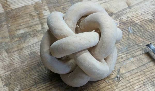
Battery Management Module Hacked For Lithium-Iron Battery Bank

In a departure from his usual repair and tear down fare, [Kerry Wong] has set out on a long-term project — building a whole-house battery bank. From the first look at the project, this will be one to watch.

To be fair, [Kerry] gave us a tease at this project a few months back with his DIY spot welder for battery tabs. Since then, he appears to have made a few crucial design decisions, not least of which is battery chemistry. Most battery banks designed for an inverter with enough power to run household appliances rely on lead-acid batteries, although lithium-ion has certainly made some inroads. [Kerry] is looking to run a fairly small 1000-watt inverter, and his analysis led him to lithium-iron cells. The video below shows what happens when an eBay pack of 80 32650 LiFePo4 cells meets his spot welder. But then the problem becomes one of sourcing a battery management system that’s up to the charge and discharge specs of his 4s battery pack. We won’t spoil the surprise for you, but suffice it to say that [Kerry] really lucked out that only minimal modifications were needed for his $9 off-the-shelf BMS module.

We’re looking forward to seeing where this build goes, not least because we’d like to build something similar too. For a more traditional AGM-based battery bank, check out this nicely-engineered solar-charged system.

Continue reading “Battery Management Module Hacked For Lithium-Iron Battery Bank”

Scribble Your Way To Quick Printed Circuit Boards

There are a variety of techniques employed by electronic constructors seeking the convenience of a printed circuit board without the inconvenience of making a printed circuit board. Dead bug style construction in which the components float on a spiders-web of soldered leads above a ground plane is one, Manhattan style construction in which pads made from small cut squares of bare copper-clad PCB are glued on top of a groundplane is another.

[Freestate QRP] has another take on this type of electronics, with what he calls “Scribble style” construction. He cuts away copper from bare board to create pads and rudimentary tracks, and for him the magic ingredient comes from his choice of an engineer’s scribe to do the job. This is where the “scribble” comes from, creating a pad is as simple as drawing it with the scribe.

Of course, this technique is not entirely new, constructors have been doing this type of work for years with Dremel tools, hand engraving tools, and similar. If you’ve ever tried to do it with a knife or scalpel you will know that it’s hardly an easy task with those hand tools so the prospect of another one doing a better job is rather interesting. He’s ready and able to demonstrate it in action, showing us a couple of RF circuits using the technique.

Have you tried this technique, or one like it? How did you get on, tell us in the comments. Meanwhile, you might like to read our own [Dan Maloney]’s look at dead bug and Manhattan construction.

Non-standard circuit boards

Non-standard Circuits: Jazz For Electrons

How creative are you when you make your circuit boards? Do you hunt around for different materials to use for the board? As long as it’s an insulator and can handle the heat of a soldering iron, then anything’s fair game. Or do you use a board at all? Let’s explore some options, both old favorites and some you may not have seen before, and see if we can get our creative juices flowing.

Transparent Circuit Boards

Let’s start with the desire to show more circuit and less board. For that we can start with [CNLohr]’s circuits on glass, usually microscope slides. What’s especially nice about his is that he provides detailed videos of the whole process, including all the failed things he tried along the way. Since he didn’t start with copper clad board, he instead glued his copper sheet to the glass using Loctite 3301. That was followed by the usual etching process, though with plenty of gotchas along the way.

In the end, he made a number of circuits, including an LED clock with the LEDs on the glass itself, and even attempted leading the community in making a glass keytar. The latter didn’t work out, but the resulting glass circuits are a work of art anyway.

What about making a transparent circuit board out of acrylic? [Frank Zhao] attempted just that by laser cutting troughs into the acrylic for the traces, and then drawing in nickel ink. But something in the ink ate into the acrylic, and as if that wasn’t bad enough, the voltage drop across the nickel was too high for his circuit. Suggestions were made in the comments for how to solve these problems, but unless we missed it, we haven’t seen another attempt yet.

But we’ve only just begun. What if you wanted even more transparency?

Continue reading “Non-standard Circuits: Jazz For Electrons”

Impressive Drawing Machine For One Made So Simply

Not all of us have CNC machines, laser cutters and 3D printers, and I’ll bet most of us didn’t start out that well equipped. The low-cost drawing machine that [jegatheesan] made for his daughter reminds us that you can prototype, and then make a functioning mechanical Da Vinci with very basic materials and mostly hand tools. He also wrote his own drawing software, with an interface that has its own simplicity.

There really are a lot of things to like about [jegatheesan]’s project. He first works out the math himself by doing something the likes of which we’ve all enjoyed, digging out the old school trigonometry and algebra books for a refresher. Then he got started on his prototype, made using a cardboard tube for the main support and straws and safety pins for the drawing arms. He already had a motor shield for his Arduino but it supported only 2 servos, so he made his own 3-servo shield. In the end, the prototype told him he had to redo some calculations, allowing him to move on to the final machine.

One thing we can say about the final machine is that hot glue must truly be the maker’s connect-all — you won’t find many screws here. Even the servos are held in place with copious quantities of glue. And the mechanism for lifting the pen is also quite clever. The whole thing is mounted on two vertical guide rods, so that it can easily slide up and down. To get it to actually move up and down, he glued a toy car wheel off-center on a servo arm. When the servo turns, the off-center wheel acts like a cam, pushing down on the wooden base to either lift the machine up or lower it down, depending on where the wheel is in its rotation.

See his hackaday.io page for the full step-by-step development process. But first check out the videos below to see how impressive such a simply made machine is in action.

Continue reading “Impressive Drawing Machine For One Made So Simply”

Tracing A Scene An Old-Fashioned Way

Taking a picture is as simple as tapping a screen. Drawing a memorable scene, even when it’s directly in front of you, is a different skill entirely. So trace it! Well, that’s kind of hard to do without appropriate preparation.

[bobsteaman]’s method is to first whip up a pantograph — it tested well with a felt marker on the end. Next, he built a camera obscura into a small wood box with a matte plexiglass top, which didn’t work quite so well. A magnifying glass above the camera’s pinhole aperture helped, but arduous testing was needed to ensure it was set at perfect position for a clear image. The matte plexiglass was also thrown out and, after some experimentation, replaced with a sheet of semi-transparent baking paper sandwiched between two pieces of clear plexiglass. The result is hard to argue with.

Continue reading “Tracing A Scene An Old-Fashioned Way”

Hack Together A Whack-A-Mole In A Box!

Here’s a project that you can throw together in an afternoon, provided you have the parts on hand, and is certain to entertain. Hackaday.io user [SunFounder] walks us through the process of transforming a humble cardboard box into a whack-a-mole game might be just the ticket to pound out some stress or captivate any children in the vicinity.

A multi-control board and nine arcade buttons are the critical pieces of hardware here, with wires and a USB cable rounding out  the rest of the electronics. Separate the button core from the upper shell, mounting the shell in the box, and connect the button core’s LED cathode to the button’s ON terminal. Repeat eight times. Solder the buttons in parallel and add some more wire to the buttons’ ON terminals to extend their reach. Repeat eight more times.

Place the finished LED+cores into the buttons and connect their ON terminals to their respective buttons on the multi control board. Now for the hard step: use a mini-USB to USB cable to connect the controller to a computer you want to use to run the game’s code in the Arduino IDE. Modify the key-mappings and away you go! Check out the build video after the break.

Continue reading “Hack Together A Whack-A-Mole In A Box!”

How Low-Power Can You Go?

[lasersaber] has a passion: low-power motors. In a bid to challenge himself and inspired by betavoltaic cells, he has 3D printed and built a small nuclear powered motor!

This photovoltaic battery uses fragile glass vials of tritium extracted from keychains and a small section of a solar panel to absorb the light, generating power. After experimenting with numerous designs, [lasersaber] went with a 3D printed pyramid that houses six coils and three magnets, encapsulated in a glass cloche and accompanied by a suitably ominous green glow.

Can you guess how much power and current are coursing through this thing? Guess again. Lower. Lower.

Under 200mV and 20nA!

Continue reading “How Low-Power Can You Go?”