[CNLohr] is no stranger to running Minecraft on some weird hardware. Earlier, he built this Linux powered microscope slide… thing to toggle LEDs with redstone levers in Minecraft. Figuring if Minecraft could run on an AVR, he decided to try the same thing on a router, a TP-LINK TL-WR841N to be specific. Like the microscope slide running Linux, this proved to be an easy task. [CNLohr] had another router he could run Minecraft on, and this one could also punch wood. There really was only one thing for him to do.
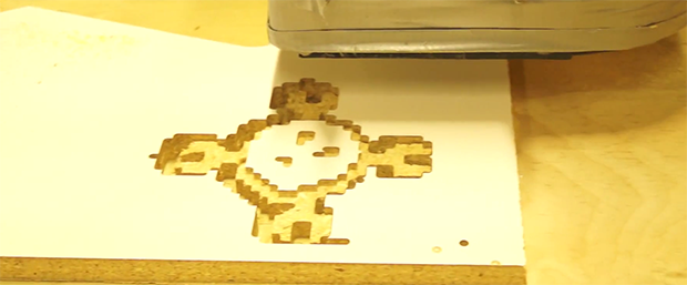
Like the microscope slide and the wireless router, [CNLohr]’s CNC router is now running a Minecraft server. The phrase, “because it’s there” comes to mind. When connected to the CNC server, the player controls a snow golem (a snowman with a jack ‘o lantern head) with a carrot. Wherever the snow golem goes, the tool head follows, allowing him to carve objects in the world, and on a sheet of MDF secured in the CNC machine.
It’s certainly an odd build, but [CNLohr] was able to carve out a pixeley, blocky Hackaday logo with the snow golem controlled CNC machine. Code here, video below.
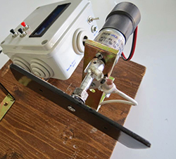 Back when electric guitars were a new thing, winding pickups was a very labor intensive and error-prone process. The number of windings could easily vary by a few hundred turns of wire, making the resulting pickup either anemic or much more powerful than the other pickups in the guitar. [Davide] is starting to wind his own pickups, and desiring a little more precision than simply guessing how many winds are on a coil