[Applied Procrastination] aka [Simen E. Sørensen] has a simple project to help those of us that struggle with early-morning zombification. By leveraging the backlight optics from a broken LCD monitor, it is possible to create an excellent diffused light source to simulate daylight, before your chosen waking time. The theory is that it is less shocking to the brain to be woken more gradually than an alarm may do. The increasing light level is to prepare the brain with a slowly increasing light level, reminiscent of daybreak, before being properly awoken by an alarm, regardless of the actual light level outdoors. This particularly useful for those of us in more northern regions, such as [Simen]’s native Norway, where mornings are very dark in the winter months.
Daylight is not purely a diffuse source however, it depends on the degree of atmospheric scattering, local reflections and such, but as far as we’re concerned here, we can just aim for as diffuse a light source a possible.
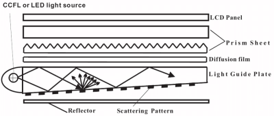
The implementation makes use of the existing LCD metal frame, the light guide panel (usually a big hunk of acrylic covered in etched markings on one side) the diffuser/brightener sheet, and the prism sheet. A white LED strip mounted around the frame edge directs light into the light guide, which with a combination of total internal reflection and scattering on one side only, effectively turns the light through 90 degrees, and spreads it out evenly across that surface. The result of this optical sandwich is flat, even light, exactly what you want for a display, and also for simulating daylight.
Nestled beneath the expected 3D printed frame, is a custom PCB derived by smooshing together the designs from the Adafruit DS3231 RTC module and the Arduino Nano, an additional push button and rotary encoder complete the minimalistic UI, and allow the device to double up as general purpose lamp during the day. Despite a few wobbles with assembling the frame, and some incorrect PCB footprinting, the whole thing came together pretty nicely. This is a perfect thing to do with broken LCD monitors, eeking out a new life and keeping the amount of landfill to a minimum.
For further details of the hardware and codes, see the Zom-b-Gone Github.
Continue reading “Banish Early Morning Zombification With The Zom-b-gone!”