Snazzy Balun Lets Ham Use Off-The-Shelf Coax

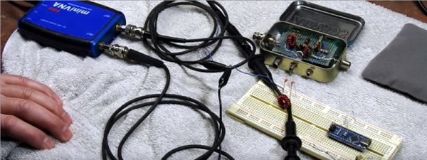
It’s a dilemma many hams face: it’s easy to find yourself with a big spool of RG-11 coax cable, usually after a big cable TV wiring project. It can be tempting to use it in antenna projects, but the characteristic impedance of RG-11 is 75 Ω, whereas the ham world is geared to 50 Ω. Not willing to waste a bounty of free coax, one ham built a custom 1:1 current balun for a 75 Ω dipole.

Converting between balanced and unbalanced signals is the job of a balun, and it’s where the device derives its name. For hams, baluns are particularly useful to connect a dipole antenna, which is naturally balanced, to an unbalanced coax feedline. The balun [NV2K] built is a bifilar 1:1 design, with two parallel wires wound onto a ferrite core. To tweak the characteristic impedance to the 75 Ω needed for his antenna and feedline, [NV2K] added short lengths of Teflon insulation to one of the conductors, which is as fussy a bit of work as we’ve seen in a while. We appreciate the careful winding of the choke and the care taken to make this both mechanically and electrically sound, and not letting that RG-11 go to waste is a plus.

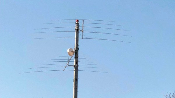
With as much effort as hams put into antenna design, there’s a surprising dearth of Hackaday articles on the subject. We’ve talked a bit about the Yagi-Uda antenna, and we’ve showcased a cool magnetic loop antenna, but there’s precious little about the humble dipole.

[via r/amateurradio]

The Early Bird Repairs A Slug

When faced with a problematic Bird slug, [Robert Meister] didn’t give up. He pecked away at the slug and brought us all along for the ride. If that sentence didn’t make sense to you, read on!

Anyone who’s been to a hamfest has seen a Bird meter. The Bird Model 43 watt meter is the defacto standard for measuring transmitter power in-line. Bird meters don’t just work from DC to light though. In fact, the model 43 itself is just a bit of transmission line and a meter movement.  The magic happens inside the swappable measurement element. These elements, affectionately called “slugs” are calibrated for a frequency band and power range. An example would be the model 4410-6, which works from 50 – 200 MHz, at up to 1 kW. Most hams have a collection of these slugs to go with the bands they transmit on.

[Robert]’s problem child was a model 100E element, good for 100 watts on 400 – 1000 MHz. The meter output seemed erratic though. A bit of troubleshooting with a second meter and a known good slug isolated the problem to the 100E. The problem was isolated to the slug, but how to fix it?

Slugs are sealed brass containers, each of which is calibrated to 5% accuracy at the factory. They are the closest thing you’ll find in the ham world to “no user serviceable parts inside”. Still, [Robert] had nothing to lose. He soaked the slug in a bit of Xylene solvent to loosen the glue holding the metal label on. Behind that were a painted screw and a hole for a calibration pot. We’re guessing the paint is Bird’s idea of tamper detection.

Pulling the screw out, and removing the nylon cover on the back of the slug revealed the real story. The slug contained a calibrated sensing loop, a diode, the calibration pot, and a terminating resistor. In [Robert]’s case, all he had to do was clean the contacts on the slug, and things worked fine.

For 11 years, anyway. After that, the slug started acting up again. Cleaning didn’t fix the problem this time. [Robert] ended up replacing the calibration potentiometer with a similar model from Digi-key. He re-calibrated the slug against his known good meter. It may not be a lab quality calibration, but this slug should be good for another few decades in his shack.

Retrotechtacular: Radio To Listen To When You Duck And Cover

CONELRAD may sound like the name of a fictional android, but it is actually an acronym for control of electronic radiation. This was a system put in place by the United States at the height of the cold war (from 1951 to 1963) with two purposes: One was to disseminate civil defense information to the population and, also, to eliminate radio signals as homing beacons for enemy pilots.

Continue reading “Retrotechtacular: Radio To Listen To When You Duck And Cover”

Homemade 6 GHz Radar, V3

The third version of [Henrik Forstén] 6 GHz frequency-modulated continuous wave (FMCW) radar is online and looks pretty awesome. A FMCW radar is a type of radar that works by transmitting a chirp which frequency changes linearly with time. Simple continuous wave (CW) radar devices without frequency modulation cannot determine target range because they lack the timing mark necessary for accurately time the transmit and receive cycle in order to convert this information to range. Having a transmission signal modulated in frequency allows for the radar to have both a very high accuracy of range and also to measure simultaneously the target range and its relative velocity.

Like the previous versions, [Henrik] designed a four-layer pcb board and used his own reflow oven to solder all the ~350 components. This process, by itself, is a huge accomplishment. The board, much bigger than the previous versions, now include digital signal processing via FPGA.

[Henrik’s] radar odyssey actually started back in 2014, where his first version of the radar was detailed and shared in his blog. A year later he managed to solve some of the issues he had, design a new board with significant improvements and published it again. As the very impressive version three is out, we wonder what version four will look like.

In the video of [Henrik] riding a bicycle in a circle in front of the radar, we can see the static light posts and trees while he, seen as a small blob, roams around:

Continue reading “Homemade 6 GHz Radar, V3”

One Man’s Tale Of EMC Compliance Testing

If you turn over almost any electronic device, you should find all those compliance logos: CE, FCC, UL, TÜV, and friends. They mean that the device meets required standards set by a particular region or testing organisation, and is safe for you, the consumer.

Among those standards are those concerning EMC, or ElectroMagnetic Compatibility. These ensure that the device neither emits RF radiation such that it might interfere with anything in its surroundings, nor is it unusually susceptible to radiation from those surroundings. Achieving a pass in those tests is something of a black art, and it’s one that [Pero] has detailed his exposure to in the process of seeing a large 3-phase power supply through them. It’s a lengthy, and fascinating post.

He takes us through a basic though slightly redacted look at the device itself, before describing the testing process, and the EMC lab. These are fascinating places with expert staff who can really help, though they are extremely expensive to book time in. Since the test involves a mains power supply he describes the Line Impedance Stabilisation Network, or LISN, whose job is to safely filter away the RF component on the mains cable, and present a uniform impedance to the device.

In the end his device failed its test, and he was only able to achieve a pass with a bit of that black magic involving the RF compliance engineer’s secret weapons: copper tape and ferrite rings. [Pero] and his colleagues are going to have to redesign their shielding.

We’ve covered our visits to the EMC test lab here before.

Radio Tuning The Quicksilver Way

Modern radios are often digital affairs, in which the frequency is derived from a stable crystal oscillator and varied through a microprocessor controlled frequency synthesiser. It won’t drift, and it’s exactly on the frequency dialed in. Older radios though relied on a tuned circuit, a combination of capacitor and inductor, for their frequency selection. If you were curious enough to peer inside — and we know you were — you’d have seen the moving vanes of a variable capacitor controlled by the tuning knob.

Of course, there is another way to adjust a tuned circuit: by changing the value of the inductor. Older car radios for instance moved a ferrite slug inside a coil to tune from station to station. But that method is not good enough for [David Mills]. Being in possession of some finely graduated syringes he decided to try liquid tuning by increasing the volume within the coil.

Solutions of salts made little difference, so he reached for some mercury. The result is an RF inductor wound round a syringe body, with a body of mercury whose position can be adjusted by the plunger. He measures the Q factor of the coil with air core or mercury core, and as the inductance decreases with more mercury, so does the Q.

We see home-made parts from time to time, and there’s nothing too special about permeability tuning. However, this unusual take on the matter makes this one rather special. We doubt we’ll see its like very often in the future.

Accidental Satellite Hijacks Can Rebroadcast Cell Towers

A lot of us will use satellite communications without thinking much about the satellite itself. It’s tempting to imagine that up there in orbit is a communications hub and distribution node of breathtaking complexity and ingenuity, but it might come as a surprise to some people that most communications satellites are simple transponders. They listen on one frequency band, and shift what they hear to another upon which they rebroadcast it.

This simplicity is not without weakness, for example the phenomenon of satellite hijacking has a history stretching back decades. In the 1980s for example there were stories abroad of illicit trans-atlantic serial links nestling as unobtrusive single carriers among the broad swathe of a broadcast satellite TX carrier.

Just sometimes, this phenomenon happens unintentionally. Our attention was drawn to a piece by [Harald Welte] on the unintended rebroadcast of GSM base station traffic over a satellite transponder, and of particular interest is the presentation from a conference in 2012 that it links to. The engineers show how they identified their interference as GSM by its timing frames, and then how they narrowed down its source to Nigeria. This didn’t give them the uplink in question though, for that they had to make a downconverter from an LNB, the output of which they coupled to an aged Nokia mobile phone with a wire antenna placed into an RF connector. The Nokia was able to decode the cell tower identification data, allowing them to home in on the culprit.

There was no fault on the part of the GSM operator, instead an unterminated port on the uplink equipment was enough to pick up the GSM signal and introduce it into the transponder as a parasitic signal for the whole of Europe and Africa to hear. Meanwhile the tale of how the engineers identified it contains enough detective work and outright hardware hacking that we’re sure the Hackaday readership will find it of interest.

If satellite hacks interest you, how about reading our thread of posts on the recapture of ISEE-3, or maybe you’d like to listen for a lost satellite from the 1960s.

Thanks [Kia] for the tip.