Dirty little secret time: although amateur radio operators talk a good game about relishing the technical challenge of building their own radio equipment, what’s really behind all the DIY gear is the fact that the really good stuff is just too expensive to buy.
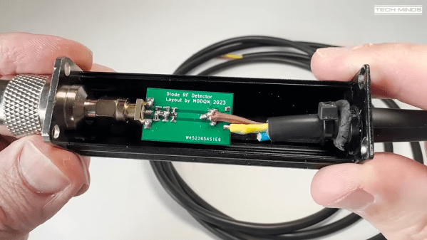
A case in point is this super-low-cost RF power sensor that [Tech Minds (M0DQW)] recently built. It’s based on a design by [DL5NEG] that uses a single Schottky diode and a handful of passive components. The design is simple, but as with all things RF, details count. Chief among these details is the physical layout of the PCB, which features a stripline of precise dimensions to keep the input impedance at the expected 50 ohms. Also important are the number and locations of the vias that stitch the ground planes together on the double-sided PCB.
While [Tech Minds]’ first pass at the sensor hewed closely to the original design and used a homebrew PCB, the sensor seemed like a great candidate for translating to a commercial PCB. This version proved to be just as effective as the original, with the voltage output lining up nicely with the original calibration curves generated by [DL5NEG]. The addition of a nice extruded aluminum case and an N-type RF input made for a very professional-looking tool, not to mention a useful one.
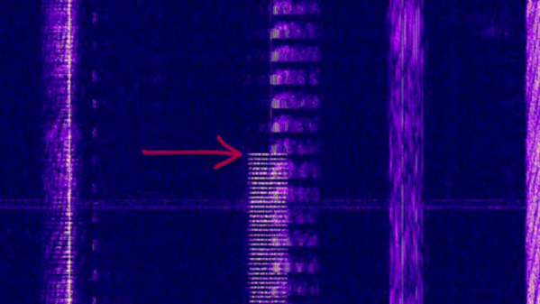
[Tech Minds] is lucky enough to live within view of QO-100, ham radio’s first geosynchronous satellite, so this sensor will be teamed up with an ADC and a Raspberry Pi to create a wattmeter with a graphical display for his 2.4-GHz satellite operations.
Continue reading “Low-Cost RF Power Sensor Gets All The Details Right”