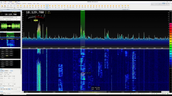
If you haven’t seen [Ken Shirriff]’s teardowns and reverse engineering expeditions, then you’re in for a treat. His explanation and demonstration of the Apollo digital ranging system is a fascinating read, even if vintage computing and engineering aren’t part of your normal fare.
The average Hackaday reader should be familiar with the concept of determining the distance of a faraway object by measuring how long it takes a sound or radio wave to be reflected, such as in sonar and radar. Going another step and measuring Doppler Shift – the difference in the returned signal’s frequency – will tell us the velocity of the object relative to our position. It’s so simple that an Arduino can do it. But in the days of Apollo, there was no Arduino. In fact, there were no Integrated Circuits. And Apollo missions went all the way to the moon- far too distant for relatively simple Radar measurements. Continue reading “The Apollo Digital Ranging System: More Than Meets The Eye”→
It’s a problem that has dogged electronic engineers since the first electrons were coaxed along a wire: that measuring instruments can themselves disrupt the operation of a circuit. Older multimeters for example had impedances low enough to pull resistor values, thus our multimeters today have high-impedance FET inputs. [Christoph] faced it with his oscilloscope probe, its input capacitance was high enough to put unacceptable load on a crystal oscillator and stop it oscillating. He thus built a FET input probe for higher RF frequencies, and its construction is an accessible view of wideband RF instrumentation design.
The circuit is a very simple one using a dual-gate FET, but the interest comes in the PCB and screening can design to ensure good RF performance. Off-the-shelf cans have four sides, so to accommodate the circuit one wall of the can had to be removed. The end result is a tiny PCB with miniature co-ax connectors for power and signal, which when characterised was found to have a 1.3 GHz bandwidth and a very low input capacitance.
Restoring a vintage radio receiver has the potential to be a fun weekend project, but it pays to know what you’re up against. Especially in the case of vacuum tube electronics, running down gremlins in the circuits isn’t always a straightforward process (also, please mind the high voltage that is present in old vacuum tube equipment). [Mr Carlson] has a knack for getting old radios humming once again, and his repair of a 1960s General Electric barn find radio receiver is a thorough masterclass in vintage electronics servicing.
Seriously, if you’ve got a spare ninety minutes, the video (after the break) is a thorough and unabridged start-to-finish diagnosis and repair of a vintage radio, and an absolute must for anyone interested in doing the same. This barn find radio was certainly showing its age, and it wasn’t long before in-circuit testing found an open filament in one of several vacuum tubes, but the radio was still stubbornly silent. Further testing revealed that the IF transformers were out of spec, requiring servicing and alignment. After fine tuning both the IF and RF sections of the radio, things were definitely looking (and sounding) better.
Fine tuning the various components in the radio went a long way to living up to its “long range” claims, and by the end of the video, it’s almost impossible to find dead air on the AM dial of this radio. If you’ve never had to make fine adjustments to a receiver, especially of this vintage, this video has all the details you’ll need. With the board exposed, [Mr Carlson] also took care of some preventative maintenance, including replacing the original filter capacitor with newer components, as well as replacing the mains safety capacitor with an even safer modern alternative.
We can’t get enough of these restorations, so make sure to check out our detailed write-up of restoring a WWII aircraft radio.
Noise is an annoying but unavoidable part of any engineering project. Fixing noise issues is hard enough, but even just measuring how much noise an amplifier adds to your signal is tricky without proper equipment like a spectrum analyzer. One other thing that makes noise measurements easier is a good, stable noise source that can serve as a reference: you first measure your amplifier without any input, and then measure it again with the noise source connected. Using a few simple formulas you can then calculate how much noise the amplifier produced.
Building a source that generates exactly the amount of noise that you want, no more and no less, is quite a challenge in itself. Several techniques exist, but [Wolfgang] over at the Electronic Projects for Fun blog decided to go for the classic method of using a vacuum diode. He describes the design and analysis of a noise source based on a 2D3B tube in a detailed article.
The tube in question is a special vacuum diode designed to be operated in saturation, meaning at a current high enough to draw away all the electrons generated by the hot filament. When running in this mode, the output current has a noise spectrum that is almost perfectly white, meaning its power level remains constant across the frequency band. [Wolfgang]’s measurements show a deviation of no more than 0.2 dB between 200 kHz and 200 MHz. This is about as close to perfect as you can get, and covers most of the frequency bands of interest to radio amateurs.
The whole project is built up inside a sturdy metal box, with extensive shielding and line filtering to keep undesired signals from contaminating the clean noise signal. A limiter is also an essential component: should the diode’s filament break, the limiter will prevent the sudden transient from reaching the spectrum analyzer and destroying its (very expensive) input stage.
[Wolfgang] has made a few other noise sources based on various components, which he compares on a separate page, although the 2D3B based one is by far the most stable. We’ve also featured a simple pink noise source, which is useful for audio measurement, as well as white noise sources designed to generate random numbers or simply to help you sleep.
[Oleg Kutkov] decided to build a wideband SDR – for satellite communication research and monitoring, you know, the usual. He decided on a battery of HackRF boards – entire eight of them, in fact. Two 1×4 and one 1×2 RF splitters and an LNA on their combined RF input made for a good start to the project, and from there, it only got more complex.
HackRF boards can be synchronized with a separate clock source, but you can’t just pull a single clock line to all of them in a star configuration. Thus, he’s built a clock distribution and amplifier board, with 4 ns propagation delay at 1 PPS, and only 10 ns delay at 10 MHz. Then, he integrated that board with the HackRF setup, adding a case, wiring up a purpose-built cable and dealing with the reflections that occurred.
HackRF boards are USB 2.0 and able to generate a stream of data up to 320 MB/s, and there’d be no viable way to aggregate eight 2.0 links into one. To solve that, he’s used eight separate PCI-E to USB 3.0 cards, each of them with one HackRF plugged in, all connected to an AMD Ryzen 9-powered PC through PCI-E risers we typically see used for mining purposes. To tie it all together, he created a gnuradio flowgraph and patched the osmocom source block to enable the external clock synchronization mechanisms he decided to use.
Each HackRF is connected to its own PCIe USB card.
In the end, [Oleg] shows us some promising results – two DVB-S transceivers visible on the waterfall display of the spectrum capture. The work is not over here, to be clear – he’s ran into a few roadblocks. The gnuradio flowgraph doesn’t lend itself well to multi-threading, even on a Ryzen 9 machine, and [Oleg] pledged to rewrite the capture mechanisms in C++ which can be nicely allocated to separate physical CPU cores, something gnuradio is apparently not quite good at.
More importantly, the spectrum captured is not continuous, and [Oleg] questions whether it can be demodulated properly. He had to resort to frequency overlaps due to upsampling, and he’s not quite sure how to compensate for that. Overall frequency stability is also in question. However, from here, seems like most of the work towards building a wideband receiver is done!
[Oleg] is typically seen on Twitter, lately doing some heavy tinkering with Starlink – as Kyiv, the city he’s currently in, is under bombardment of Russian Armed Forces. We can only respect and appreciate the dedication. In January, we’ve covered his work on an USA-imported Tesla LTE modem replacement to fix LTE band incompatibilities in Ukraine, and his blog is a treasure trove of experiments that we are yet to properly comb through, from astrophysics and satellite work to RS485 networks and Linux driver writing.
If there’s one thing that amateur radio operators are good at, it’s turning just about anything into an antenna. And hams have a long history of portable operations, too, where they drag a (sometimes) minimalist setup of gear into the woods and set up shop to bag some contacts. Getting the two together, as with this field-portable antenna made from a tape measure, is a double win in any ham’s book.
For [Paul (OM0ET)], this build seems motivated mainly by the portability aspect, and less by the “will it antenna?” challenge. In keeping with that, he chose a 50-meter steel tape measure as the basis of the build. This isn’t one of those retractable tape measures, mind you — just a long strip of flexible metal on a wind-up spool in a plastic case. His idea was to use the tape as the radiator for an end-fed halfwave, or EFHW, antenna, a multiband design that’s a popular option for hams operating from the 80-m band down to the 10-m band. EFHW antennas require an impedance-matching transformer, a miniature version of which [Paul] built and tucked within the tape measure case, along with a BNC connector to connect to the radio and a flying lead to connect to the tape.
Since a half-wave antenna is half the length of the target wavelength, [Paul] cut off the last ten meters of the tape to save a little weight. He also scratched off the coating on the tape at about the 40-meter mark, to make good contact with the alligator clip on the flying lead. The first video below details the build, while the second video shows the antenna under test in the field, where it met all of the initial criteria of portability and ease of deployment.
It’s a problem we all have at one time or another: your five-meter radio astronomy dish gets out of calibration and you don’t have a ridiculously expensive microwave holography rig on hand to diagnose it. OK, maybe this isn’t your problem, but when [Joe Martin]’s parabolic antenna got out of whack, he set out to diagnose and repair it, and then wrote up how he did it. You can download the PDF from his radio astronomy articles collection.
At the heart of the measurement rig is a laser rangefinder connected to a Porcupine Labs interface that passes the data on to a Pi 4. This is placed on the end of a two-degree-of-freedom servo gimbal that scans over the surface of the dish, measuring its shape. After measuring and math, [Joe] found out that it’s a little bit long here and short there, he attached two cables with turnbuckles to the front of the dish and pulled it back into shape — the sort of thing that you should probably only do if you’ve got a measurement rig already set up.
The Fluke rangefinder and Porcupine labs interface combo is pretty sweet, but it comes with a fairly hefty price tag. (Nothing compared to a professional dish measurement rig, we presume.) We’ve seen a few attempt at hacking into el-cheapo laser rangefinders, but other than [iliasam]’s heroic effort where he ended up writing his own firmware, it doesn’t seem like there are any successes. A shame, because applications like [Joe]’s prove that there’s a need for one. Let us know if there’s anything we missed?