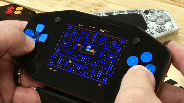
Maker Faire NY: Getting Physical With Minecraft

If you’ve been hanging around Hackaday for a while, you’ve likely seen a few attempts to bridge the real world with the voxel paradise that is Minecraft. In the past, projects have connected physical switches to virtual devices in the game, or took chunks of the game’s blocky landscape and turned it into a 3D printable file. These were interesting enough endeavors, but fairly limited in their scope. They assumed you had an existing world or creation in Minecraft that you wanted to fiddle with in a more natural way, but didn’t do much for actually playing the game.

But “Physical Minecraft” presented at the 2018 World Maker Faire in New York, offered a unique way to bring players a bit closer to their cubic counterparts. Created by [Manav Gagvani], the physical interface has players use a motion detecting wand in combination with an array of miniature Minecraft blocks to build in the virtual world.

The wand even detects various gestures to activate an array of “Spells”, which are effectively automated build commands. For example, pushing the wand forward while making a twisting motion will automatically create a tunnel out of the selected block type. This not only makes building faster in the game, but encourages the player to experiment with different gestures and motions.

A Raspberry Pi 3 runs the game and uses its onboard Bluetooth to communicate with the 3D printed wand, which itself contains a MetaWear wearable sensor board. By capturing his own moves and graphing the resulting data with a spreadsheet, [Manav] was able to boil down complex gestures into an array of integer values which he plugged into his Python code. When the script sees a sequence of values it recognizes, the relevant commands get passed onto the running instance of Minecraft.

You might assume the wand itself is detecting which material block is attached to it, but that bit of magic is actually happening in the base the blocks sit on. Rather than trying to uniquely identify each block with RFID or something along those lines, [Manav] embedded an array of reed switches into the base which are triggered by the presence of the magnet hidden in each block.

These switches are connected directly to the GPIO pins of the Raspberry Pi, and make for a very easy way to determine which block has been removed and installed on the tip of the wand. Things can get tricky if the blocks are put into the wrong positions or more than one block are removed at a time, but for the most part it’s an effective way to tackle the problem without making everything overly complex.

We’ve often talked about how kid’s love for Minecraft has been used as a way of getting them involved in STEM projects, and “Physical Minecraft” was a perfect example. There was a line of young players waiting for their turn on the wand, even though what they were effectively “playing” was the digital equivalent of tossing rocks. [Manav] would hand them the wand and explain the general idea behind his interface, reminding them that the blocks in the game are large and heavy: it’s not enough to just lower the wand, it needs to be flicked with the speed and force appropriate for the hefty objects their digital avatar is moving around.

Getting kids excited about hardware, software, and performing physically demanding activities at the same time is an exceptionally difficult task. Projects like “Physical Minecraft” show there can be more to playing games than mindless button mashing, and represent something of a paradigm shift for how we handle STEM education in an increasingly digital world.

Hack My House: Raspberry Pi As Infrastructure

I finally had my own house. It was a repossession, and I bought it for a song. What was supposed to be a quick remodel quickly turned into the removal of most of the drywall in the house. There was a silver lining on this cloud of drywall dust and loose insulation. Rather than constantly retro-fitting cabling and gadgets in as needed, I could install everything ahead of time. A blank canvas, when the size of a house, can overwhelm a hacker. I’ve spent hours thinking through the infrastructure of my house, and many times I’ve wished for a guide written from a hacker’s perspective. This is that guide, or at least the start of it.

What do you want your smart house to do? And what do you want to be able to do in your smart house? For example, I wanted to be able to upgrade my cheap 120 V welder to a beefier 240 V model, so adding a 240 V plug in the garage was a must. As a bonus, that same 240 V circuit could be used for charging an electric car, if ever one is parked there.

“Ethernet everywhere” was my mantra. Try to imagine everywhere you might want to plug in a desktop, a laptop, an access point, or even a VoIP phone. I decided I wanted at least two Ethernet drops to each room, and tried to imagine the furniture layout in order to put them in convenient places.

Continue reading “Hack My House: Raspberry Pi As Infrastructure”

Easy GUI Front Ends For Arduino, Rasberry Pi, And More With MyOpenLab

If you want to integrate a nice graphical interface with a microcontroller or single-board computer for a useful piece of custom equipment, how will you go about it? MyOpenLab is a platform that makes it easy to design virtual interfaces your electronic builds. If you want controls and readouts for Arduino, Raspberry Pi, Android, or anything with a serial port, this is worth a try.

MyOpenLab reminds me of LabView. Not so much modern LabView with all of its add-ons and extras, but LabView back when it did just a few things but did them really well. The open source MyOpenLab project has been around for a while. The website and documentation are not in English, which may have kept some people from giving it a try, but the software itself is available in German, English, and Spanish. I took the plunge and found the language barrier didn’t cause me trouble.

As an example of what you can do, image you want to build a custom bench tool. You build virtual device (they call it a “VirtualMachine”) that uses your computer as the control panel and readout, and your electronic project as the physical interface. In myOpenLab your device will consist of two parts: a diagram and a front panel. Some things only live on the diagram, like a timer or a connection to an Arduino. But some things live on both like switches, LEDs, graphs, and so on. You can connect all the little boxes together to build up applications. They can stand alone, but the power comes in being able to connect to an Arduino or Raspberry Pi (or a few other options) for I/O.

Continue reading “Easy GUI Front Ends For Arduino, Rasberry Pi, And More With MyOpenLab”

Learn ARM Assembly With The Raspberry Pi

We live in a time when you don’t have to know assembly language to successfully work with embedded computers. The typical processor these days has resources that would shame early PCs and some of the larger ones are getting close to what was a powerful desktop machine only a few years ago. Even so, there are some cases where you really want to use assembly language. Maybe you need more speed. Or maybe you need very precise control over timing. Maybe you just like the challenge. [Robert G. Plantz] from Sonoma State University has an excellent book online titled “Introduction to Computer Organization: ARM Assembly Langauge Using the Raspberry Pi.” If you are interested in serious ARM assembly language, you really need to check out this book.

If you are more interested in x86-64 assembly and Linux [Plantz] has you covered there, too. Both books are free to read on the Internet, and you can pick up a printed version of the Linux book for a small payment if you want.

Continue reading “Learn ARM Assembly With The Raspberry Pi”

Raspberry Pi Projection Mapping Crash Course

Projection mapping might not be a term you’re familiar with, but you’ve certainly seen the effect before. It’s when images are projected onto an object, usually one that has an interesting or unusual shape, to create an augmented reality display. Software is used to map the image or video to the physical shape it’s being projected on, often to surreal effect. Imagine an office building suddenly being “painted” another color for the Holidays, and you’ll get the idea.

This might seem like one of those things that’s difficult to pull off at the hobbyist level, but as it turns out, there’s a number of options to do your own projection mapping with the lowly Raspberry Pi. [Cornelius], an avid VJ with a penchant for projection mapping, has done the legwork and put together a thorough list of different packages available for the Pi in case you want to try your hand at the futuristic art form. Many of them are even open source software, which of course we love around these parts.

[Cornelius] starts by saying he’s had Pis running projection installations for as long as three years, and while he doesn’t promise the reader it’s always the best solution, he says its worth getting started on at least. Why not? If the software’s free and you’ve already got a Raspberry Pi laying around (we know you do), you just need a projector to get into the game.

There’s a lot of detail given in the write-up, including handy pro and con lists for each option, so you should take a close look at the linked page if you’re thinking of trying your hand at it. But the short version is that [Cornelius] found the paid package, miniMAD, to be the easiest to get up and running. The open source options, ofxPiMapper and PocketVJ, have a steeper learning curve but certainly nothing beyond the readers of Hackaday.

To make things easier, [Cornelius] even goes on to give the reader a brief guide on setting up ofxPiMapper, which he says shouldn’t take more than 30 minutes or so using its mouse and keyboard interface. It would be interesting to see somebody combine this with the Raspberry Pi integrated projector we saw a couple years back to make a highly portable mapping setup.

Adding 3D Printer Power And Light Control To OctoPrint

OctoPrint is a great way to monitor your printer, especially with the addition of a webcam. Using a tablet or mobile phone, you can keep an eye on what the printer is doing from anywhere in the house (or world, if you take the proper precautions), saving you from having to sit with the printer as if it’s an infant. But simply watching your printer do its thing is only a small slice of the functionality offered by OctoPrint’s vast plugin community.

As [Jeremy S Cook] demonstrates, it’s fairly easy to add power control for the printer and auxiliary lighting to your OctoPrint setup. Being able to flick the lights on over the print bed is obviously a big help when monitoring it via webcam, and the ability to turn the printer off can provide some peace of mind after the print has completed. If you’re particularly brave it also means you could power on the printer and start a print completely remotely, but good luck if that first layer doesn’t go down perfectly.

In terms of hardware, you only need some 3.3V relays for the Raspberry Pi running OctoPrint to trigger, and an enclosure to put the wiring in. [Jeremy] uses only one relay in this setup to power the printer and lights at once, but with some adjustment to the software, you could get independent control if that’s something you’re after.

On the software side [Jeremy] is using an OctoPrint plugin called “PSU Control”, which is actually intended for controlling an ATX PSU from the Pi’s GPIO pins, but the principle is close enough to throw a relay. Other plugins exist which allow for controlling a wider away of devices and GPIO pins if you want to make a fully remote controlled enclosure. Plus you can always whip up your own OctoPrint plugin if you don’t find anything that quite meets your switching needs.

[Jeremy] previously documented his unique mount to keep his Raspberry Pi and camera pointed at his printer, which is naturally important if you want to create some cool videos with Octolapse.

Continue reading “Adding 3D Printer Power And Light Control To OctoPrint”

No Signal For Your Radio-Controlled Watch? Just Make Your Own Transmitter

You can win any argument about the time when you have a radio controlled watch. Or, at least, you can if there’s any signal. [Henner Zeller] lives in a place where there is no reception of the DCF77 signal that his European wristwatch expects to receive. Consequently, he decided to make his own tiny transmitter, which emulates the DCF77 signal and allows the watch to synchronise.

A Raspberry Pi Zero W is the heart of the transmitter, and [Henner] manages to coax it into generating 77500.003Hz on a GPIO pin – close enough to the 77.5kHz carrier that DCF77 uses. The signal is AM, and transmits one bit/s, repeating every minute. A second GPIO performs the required attenuation, and a few loops of wire are sufficient for an antenna which only needs to work over a few inches. The Raspberry Pi syncs with NTP Stratum 1 servers, which gives the system time an accuracy of about ±50ms. The whole thing sits in a slick 3D printed case, which provides a stand for the watch to rest on at night; this means that every morning it’s synchronised and ready to go.

[Henner] also kindly took the time to implement the protocols for WWVB (US), MSF (UK) and JJY (Japan). This might be just as well, given that we recently wrote about the possibility of WWVB being switched off. Be sure to check the rules in your area before giving this a try.

We’ve seen WWVB emulators before, like this ATtiny45 build, but we love that this solution is an easy command line tool which supports many geographical locations.