A research paper titled Biological Organisms as End Effectors explores the oddball approach of giving small animals jobs as grippers at the end of a robotic arm. Researchers show that pill bugs and chitons — small creatures with exoskeletons and reflexive movements — have behaviors making them useful as grippers, with no harm done to the creatures in the process. The prototypes are really just proofs of concept, but it’s a novel idea that does work in at least a simple way.
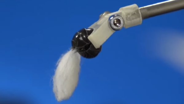
Pill bugs reflexively close, and in the process can grasp and hold lightweight objects. The release is simply a matter of time; researchers say that after about 115 seconds a held object is released naturally when the pill bug’s shell opens. While better control over release would be good, the tests show basic functionality is present.
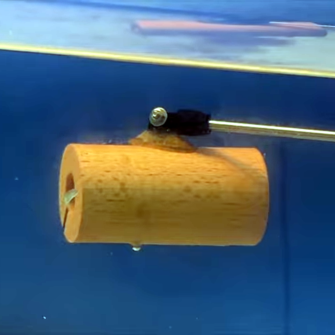
Another test involves the chiton, a small mollusk that attaches to things with suction and can act as an underwater end effector in a similar way. Interestingly, a chiton is able to secure itself to wood and cork; materials that typical suction cups do not work on.
A chiton also demonstrates the ability to manipulate a gripped object’s orientation. Chitons seek dark areas, so by shining light researchers could control in which direction the creature attempts to “walk”, which manipulates the held object. A chiton’s grip is strong, but release was less predictable than with pill bugs. It seems chitons release an object more or less when they feel like it.
This concept may remind readers somewhat grimly of grippers made from dead spiders, but researchers emphasize that we have an imperative to not mistreat these living creatures, but to treat them carefully as we temporarily employ them in much the same manner as dog sleds or horses have been used for transportation, or carrier pigeons for messages. Short videos of both pill bug and chiton grippers are embedded below, just under the page break.
Continue reading “Pill Bugs And Chitons Get Jobs As Tiny Grippers”