You may think you’ve built a power supply for your bench. Heck, we all do. But until you check out [Denis]’s bench power supply build, you may not even know what you’re missing.
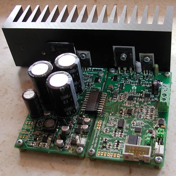
[Denis]’s design is nearly entirely modular and targeted to the intermediate builder. It’s built on easily available parts and through-hole components. It’s got an Arduino running as the brains, so you’re going to be able to hack on the code when you feel like tweaking it. But easy doesn’t mean light on features. Let’s walk through the build together.
It starts off with a pre-regulator: a switching MOSFET that gets the voltage down to just a couple volts above the target value. Then it’s off to the post-regulator that includes all of the fine adjustments, the DAC and ADC interfacing to the microcontroller, and some fancy features like a “down-programmer” that turns the output off extra quickly.
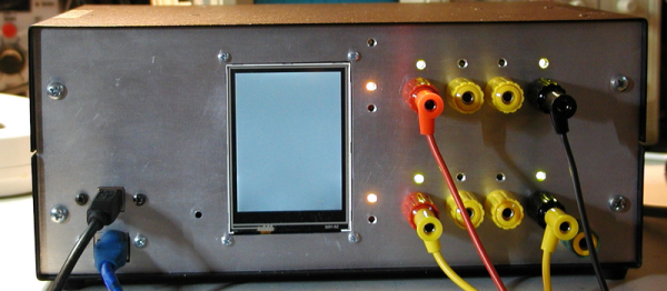
On the user end of things, [Denis] made a very sleek board that incorporates a TFT touchscreen for the controls, Arduino connections, and the obligatory banana plug outputs. There’s opto-isolation on the SPI bus, a real-time clock, and a bunch more goodies on board. He’s in his third revision of this module, and that level of refinement shows. It’s even SCPI compliant, meaning you can control remotely using an industry-standard protocol.
So what would you do with a ridiculously fancy power supply under microcontroller control? Test out battery charging algorithms? Program test routines to see how your devices will work as their batteries drain out? We have no idea, but we know we want one!
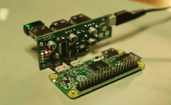
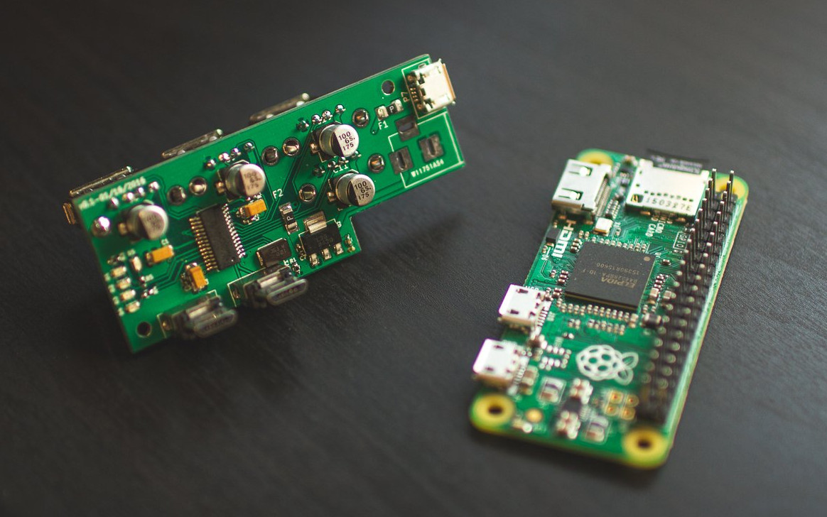
[Sean Hodgins’] acute approach is orthogonal to most of the other hubs we’ve seen. He’s mating the hub at right angles to the Zero. The hub plugs into both the on-the-go USB port and the USB power port. No extra cables or wiring needed. [Sean] plans to release the design on GitHub after his Kickstarter campaign ends. He’s supplying bare boards for those who like the smell of solder paste.
This project nicely triangulates the issues of adding a hub to the Zero. The physical connection is solid with the boards connecting via the USB connectors. Power is supplied through the hub the way the Pi expects, which means all the protections the Pi Foundation built into the onboard conditioning are left in place. This also reduces surge problems that might occur when back powering through a hub and hot swapping USB devices. Another neat feature is the notched corner leaving the HDMI port accessible. Similarly, the Pi’s GPIO pins are free of encumbrance. One drawback is the hub is fused at 2 amps, just like the Pi. It would be nice to have a little more headroom for power hungry USB devices. Maybe another 0.5 amp to allow for the Zero’s usage.
I keep up with the trends in 3D printing reasonably well. The other day my friend mentioned that filament thickness sensing had been added to the latest version of the Marlin firmware. I had no idea what it was, but it certainly sounded cool. I had to find out more.
In industrial settings, filament is made by pulling extruding molten plastic at a certain speed into a cooling bath. The nozzle for 2.85mm filament and 1.75 mm filament is actually the same size, but the filament is stretched more or less as it leaves the nozzle. By balancing these three variables the extrusion machine can produce any size filament desired. Like any mechanical system, it needs constant adjustment to maintain that balance. This is usually done by measuring the filament with a laser after it has cooled, and then feeding this information back into the system. The better filament manufacturers have multiple lasers and very fast feedback loops. Some of the best offer +-0.04mm or less variation in thickness between any two points on the filament. Some of the worst have larger errors such as +-.10mm. Because the plastic is fed into the extruder at a fixed linear speed, this makes a variation in the volume of the plastic coming out of the nozzle per second. With the best we see a 4.41% variation in the volume of plastic extruded. With the worst we start to see 10.51% or more.
Filament variation showing up as a cosmetic defect.
A printer is dumb. It works under the assumption that it is getting absolutely perfect filament. So when it gets 10.51% more plastic, it simply pushes it out and continues with its life. However, if the filament is off enough, this can actually show up as a visible defect on the print. Or in worse cases, cause the print to fail by over or under extrusion of plastic.
So, what does a filament thickness sensor do to correct this issue? To start to understand, we need to look at how the filament is dealt with by the software. When the slicer is compiling the G-code for a 3D print, it calculates the volume of plastic it needs in order to deposit a bead of plastic of a certain width and of a certain height per mm of movement. That was a mouthful. For example, when a printer printing 0.2mm layers moves 1mm it wants to put down a volume that’s 1.0mm long x 0.4mm wide x 0.2mm high. The filament being pushed into the nozzle has a volume per mm determined by the diameter of the filament.
The volume out per mm of filament in.
The equation we are trying to balance.
Our goal is to integrate the thickness sensor into these functions to see what the thickness sensor is doing. This is a linear equation, so there’s nothing fancy here. Now, the layer height, layer width, and length of the move are determined by settings and model geometry respectively. These are fixed numbers so we don’t care about them. That leaves us the diameter of the filament and the length of filament extruded. As we mentioned before, typically the filament is assumed to be a fixed diameter. So all the software has to calculate is the length of filament that needs to be extruded per mm of combined movement in the x and y so that our volumes match.
But, we know that one of these variables is actually changing per millimeter as well. The filament diameter! So now we have a problem. If the filament diameter is changing all the time, our equation will never balance! In order to fix this we can add a multiplier to our equation. Since we have no control over the width of the filament we can’t modify that value. However, if we know the width of the filament, and we know the value its supposed to be, we can change the length of the filament extruded. This is because unlike the filament, we have control over the stepper motor that drives the extruder. This value is called the extrusion multiplier, and its determination is what the thickness sensor is all about.
So all the filament sensor does is measure the filament’s current diameter. It takes expected diameter and divides it by the value it just measured to get a simple percentage. It feeds that number back into our system as the extruder multiplier and slows or speeds up the stepper motor as needed. Pretty simple.
The ideal filament the printer thinks it is seeing.
The printer is unable to compensate for the variations.
By adjusting with the extrusion multiplier the printer is able to approximate perfect filament.
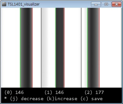
Shadows on the sensor from [inornate]’s variation.There are a few thickness sensors being toyed with right now. The first, as far as I can tell; let me know if I am wrong in the comments, was by [flipper] on thingiverse. He is in his third version now. The sensor works by casting a shadow of the filament as it passes by onto an optical sensor. The firmware then counts the pixels and works backwards to get the diameter. This value is sent to the Marlin firmware on the printer which does the rest. As is usual and wonderful in the open source community, it wasn’t long before others started working on the problem too. [inoranate] improved on the idea by casting more shadows on the sensor. The technique is still brand new, but it will be interesting to see what benefits it reaps.
Now comes the next question,”Is it worth upgrading my printer with a thickness sensor?” If you typically run poor filament, or if you extrude your own, yes. The current sensors can only measure +- .02mm. So for the best filament, you won’t really see a difference, but for worse stuff, you might. The latest firmware of the Lyman filament extruder, for making your own filament, also supports these sensors, letting you feed back into your production system like the industrial machines. All in all a very interesting development in the world of 3D printers.
My DSL line downloads at 6 megabits per second. I just ran the test. This is over a pair of copper twisted wires, the same Plain Old Telephone Service (POTS) twisted pair that connected your Grandmother’s phone to the rest of the world. In fact, if you had that phone you could connect and use it today.
I can remember the old 110 bps acoustic coupler modems. Maybe some of you can also. Do you remember upgrading to 300 bps? Wow! Triple the speed. Gradually the speed increased through 1200 to 2400, and then finally, 56.6k. All over the same of wires. Now we feel short changed if were not getting multiple megabits from DSL over that same POTS line. How can we get such speeds over a system that still allows your grandmother’s phone to be connected and dialed? How did the engineers know these increased speeds were possible?
Claude Shannon with his maze running mechanical mouse
The answer lies back in 1948 with Dr. Claude Shannon who wrote a seminal paper, “A Mathematical Theory of Communication”. In that paper he laid the groundwork for Information Theory. Shannon also is recognized for applying Boolean algebra, developed by George Boole, to electrical circuits. Shannon recognized that switches, at that time, and today’s logic circuits followed the rules of Boolean Algebra. This was his Master’s Thesis written in 1937.
Shannon’s Theory of Communications explains how much information you can send through a communications channel at a specified error rate. In summary, the theory says:
There is a maximum channel capacity, C,
If the rate of transmission, R, is less than C, information can be transferred at a selected small error probability using smart coding techniques,
The coding techniques require intelligent encoding techniques with longer blocks of signal data.
What the theory doesn’t provide is information on the smart coding techniques. The theory says you can do it, but not how.
In this article I’m going to describe this work without getting into the mathematics of the derivations. In another article I’ll discuss some of the smart coding techniques used to approach channel capacity. If you can understand the mathematics, here is the first part of the paper as published in the Bell System Technical Journal in July 1948 and the remainder published later that year. To walk though the system used to fit so much information on a twisted copper pair, keep reading.
While laser cutting remains the dominant force for rapid prototyping anything made of plastic, MDF or wood, the real holy grail is the ability to cut metal — something most laser cutters are just not capable of.
In the industry, this is done using extremely high-powered laser cutters, plasma cutters, or water jet cutters. All of which are very pricey equipment for a hacker. Until now anyway. Introducing the Tinijet, the missing tool for affordable water jet cutting.
We first covered this project a few years ago when it was just a university research project called Hydro — it’s since evolved immensely, and will be available for sale very soon.
USB has been on our desktops and laptops since about 1997 or so, and since then it has been the mainstay of computer peripherals. No other connector is as useful for connecting mice, keyboards, webcams, microcontroller development boards, and everything else; it’s even the standard power connector for phones. The latest advance to come out of the USB Implementers Forum is the USB Type-C connector, a device with gigabits of bandwidth and can handle enough current to power a laptop. It’s the future, even if Apple’s one-port wonder isn’t.
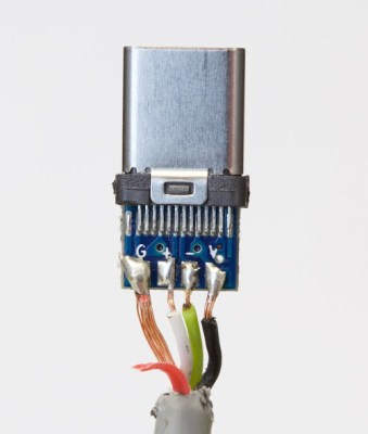
The cable of the future is, by default, new. This means manufacturers are still figuring out the port, and how to wire it up. You would think remembering ‘red = power, black = ground’ is easy, but some manufacturers get it so terribly wrong.
The cable in question was a SurjTech 3M cable that has thankfully been taken down from Amazon. Swapping GND and Vbus weren’t the only problem – the SuperSpeed wires were missing, meaning this was effectively only a USB 2 cable with a Type-C connector. The resistor required by USB spec was the wrong value, and was configured as a pull-down instead of a pull-up.
This isn’t an issue of a cable not meeting a design spec. Ethernet cables, specifically Cat6 cables, have been shown to work but fail to meet the specs for Cat6 cables. That’s shady manufacturing, but it won’t break a computer. This is a new low in the world of computer cables, but at least the cable has disappeared from Amazon.
If you read my first post about a simple CPLD do-it-yourself project you may remember that I seriously wiffed when I made the footprint 1” wide, which was a bit too wide for common solderless breadboards. Since then I started over, having fixed the width problem, and ended up with a module that looks decidedly… cuter.
To back up a little bit, a Complex Programmable Logic Device (CPLD) is a cool piece of hardware to have in your repertoire and it can be used to learn logic or a high level design language or replace obsolete functions or chips. But a CPLD needs a little bit of support infrastructure to become usable, and that’s what I’ll be walking you through here. So if you’re interested in learning CPLDs, or just designing boards for them, read on!

 [Sean Hodgins’] acute approach is orthogonal to most of the other hubs we’ve seen. He’s mating the hub at right angles to the Zero. The hub plugs into both the on-the-go USB port and the USB power port. No extra cables or wiring needed. [Sean] plans to release the design on GitHub after his





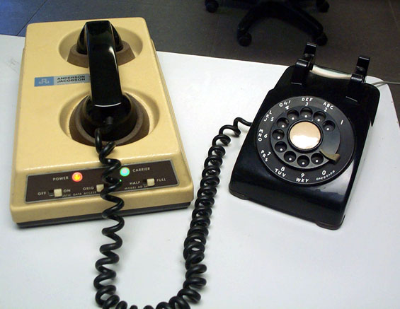 I can remember the old 110 bps acoustic coupler modems. Maybe some of you can also. Do you remember upgrading to 300 bps? Wow! Triple the speed. Gradually the speed increased through 1200 to 2400, and then finally, 56.6k. All over the same of wires. Now we feel short changed if were not getting multiple megabits from DSL over that same POTS line. How can we get such speeds over a system that still allows your grandmother’s phone to be connected and dialed? How did the engineers know these increased speeds were possible?