The name Other Machine Co. is now dead. In a post to the company blog, Other Machine Co. is now Bantam Tools. This news comes just months after the announcement that [Bre Pettis], one-third of the founders of MakerBot, investor in Glowforge, and undeservingly the most hated man in the 3D printer community, purchased Other Machine Co.
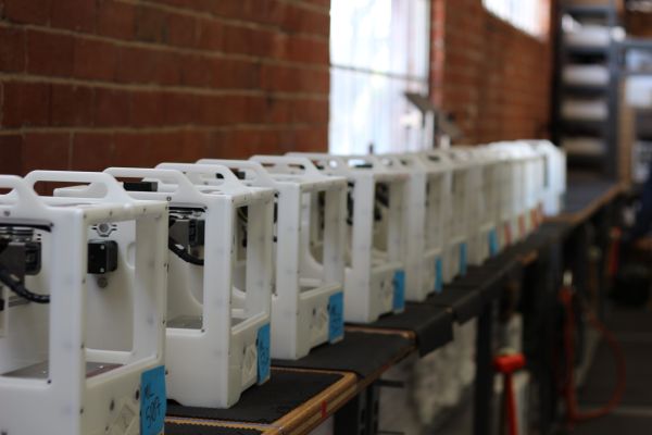
Over the past few years, the Othermill, Other Machine Co.’s main product, has gained a reputation for being a very, very nice CNC mill capable of producing PCBs with 6 mil trace and space. Additionally, the Othermill was excellent at very fine CNC work including wax carving jewelry, very neat inlay work on wood, and any other CNC task that doesn’t involve anything harder than aluminum and can fit inside the machine itself.
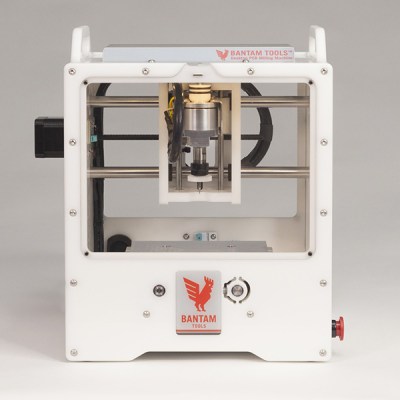 As of right now, the only change to the Othermill is the name — it’s now the Bantam Tools Desktop PCB Milling Machine. According to a Wired press release, this name change also comes with a change in focus. Bantam Tools will not focus on hobbyist makers, but instead to professionals that need PCBs and other small milling jobs done right now. For the record, I cannot recall the Othermill ever being advertised directly to ‘hobbyist makers’ — it has always seemed the target audience was professionals, or at least people who would make money from the stuff produced on their mill.
Other changes to the Othermill have been in the works for months. Since the time of the acquisition, Other Machine Co. / Bantam have introduced a PCB probing system, a desperately needed fine dust collection system, and automated material thickness probing. These new projects for Bantam mills are compatible with the old Othermill.
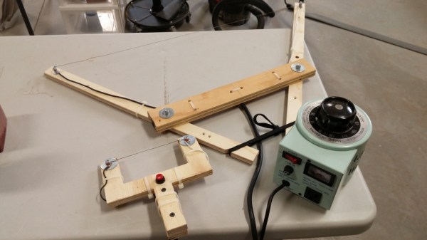
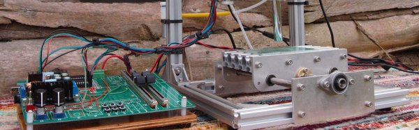
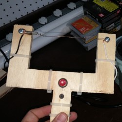 [Bithead] built two hot wire cutters with nichrome wire. The first was small, but the second was larger and incorporated some design refinements. He also got an important safety reminder when he first powered on with his power supply turned up too high; the wire instantly turned red and snapped with an audible bang. He belatedly realized he was foolishly wearing neither gloves nor eye protection.