[Project 326] wanted to know exactly what gas was in some glass tubes. The answer, of course, is to use a spectrometer, but that’s an expensive piece of gear, right? Not really. Sure, these cheap devices aren’t perfect, but they are serviceable and, as the video below shows, there are ways to work around some of the limitations.
The two units in question are “The Little Garden” spectrometer and a TLM-2. Neither are especially sensitive, but both are well under $100, so you can’t expect much. Because the spectrometers were not very sensitive, a 3D printed jig and lens were used to collect more light and block ambient light interference. The jigs also allowed the inclusion of special filters, which enhanced performance quite a bit. The neon bulbs give off the greatest glow when exposed to high voltage. Other bulbs contain things like helium, xenon, and carbon dioxide. There were also tubes with mercury vapor and even deuterium.
We’ll admit it. Not everyone needs a spectrometer, but if you do, there’s a lot of really interesting info on how to get the most out of these cheap devices. Apparently, [Project 326] was frustrated that he couldn’t buy an X-ray spectrometer and has vowed to create one, so we’ll be interested to see how that goes.
It’s not news that Leonardo DaVinci was somewhat ahead of his time, and over the centuries many of the creations in his sketchbooks have been created and proved quite functional. The guys from the YouTube channel How To Make Everything have been looking at one such sketch, a screw thread-cutting machine. At first glance, it seems a little flawed. Threads are hard to make by hand, and you can see that this thread-cutting machine needs two identical threads operating as a reference to make it work. However, as the guys demonstrate, you can create threads by hand using simple methods.
Starting with an offset blade mounted on a block with a hole through it, a dowel can be scribed with a starter thread. This can then be worked by hand to cut enough of a groove for the application. They demonstrated that the machine was viable using nothing but wood for construction. A metal blade was mounted, and some preload force was applied to it with a spring. The dowel to be cut was loaded, and the machine ran back and forth enough times to create a very nice-looking screw thread. And once you’ve made two identical threaded dowels, you can use them to upgrade the machine or even build a second. Once you have a repeatable way to make such threads, all kinds of applications become more accessible. Need a bench vice? No problem now!
Whilst the demonstration doesn’t precisely follow the plans laid out by the master inventor, they aren’t all that clear on the cutting tool after all, it’s nice to see people still wanting to build his ideas, and we’ll certainly be following along.
Developing your own film is an unabashedly analog process, which is one of the reasons people still gravitate towards it. After spending all day pushing buttons and looking at digital displays, spending some quiet time in the dark with pieces of paper and chemicals can be a way to decompress. But that doesn’t mean there isn’t room for a bit of modern digital convenience.
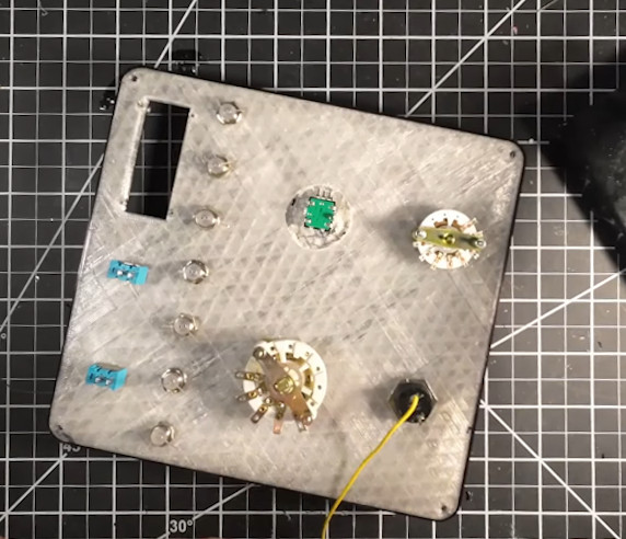
Specifically, [John Jones] wanted a timer that offered more features than his old school analog model, so he decided to build one himself. He took the long away around to make sure the end result would be a tool he could rely on, which meant getting a custom PCB made, 3D printing a case to fit in with his existing workspace, and designing a control panel that he could operate in the dark.
The PCB plays host to an ESP32 development board and an I/O expander that connects up to the array of LEDs, switches, and buttons on the front panel. The bottom-half of of the 3D printed enclosure is pretty simple, but the control panel is quite a piece of work.
Borrowing a trick from the flight sim community, [John] switched over to a clear filament after laying down the first few layers of the panel. This essentially created an integrated light diffuser, and with the addition of a few red LEDs, he had very slick backlit labels on his panel with relatively minimal effort.
Opening up the device reveals a Tuya BT17L Bluetooth module, the hackable nature of which due to other projects prompted a port of a previous Find My project which provided open source access to the network. The result is as he describes, the world’s chunkiest key finder, and also we’re guessing the one with one of the longest battery lives too.
The European budget supermarkets are well known for their budget bargain aisles, and Lidl’s Parkside range has some surprisingly robust tools among it. They might not quite be up to replacing IKEA in the hacker source stakes, but those of us who live in countries served by them know to keep an eye out in the hope of fresh gems alongside those awesome AlpenFest apple crumble cakes. This one certainly isn’t the first Parkside hack we’ve seen.
Most of us have some form of an on-the-go toolkit, but how much thought have we put into its contents? There’s a community of people who put a lot of thought into this subject, and EMF Camp have put up one of their talks from earlier in the summer in which [Drew Batchelor] sets out their manifesto and introduces tinytoolk.it, a fascinating resource.
The talk is well worth a watch, as rather than setting the tools you should be carrying, it instead examines the motivations for your kit in the first place, and how to cull those which don’t make the grade. If an item seems to see little use, put a piece of tape with the date on it every time it comes out, to put a number on it. As an example he ended up culling a multi-tool from his kit, not because it’s not an extremely useful tool, but because he found everything it did was better done by other items in the kit.
It’s probable we’ll all look at our carry-around kit with new eyes after watching this, it’s certain that ours could use a few tweaks. What’s in your kit, and how could you improve it? Let us know in the comments.
Although less popular these days, wire-wrap is still a very relevant, easily reversible solder-free way to assemble (prototype) systems using wire-wrap wire and a wire-wrap tool. This latter tool can be either a hand or powered tool, but all it has to do is retain the stripped wire, fit around the wire-wrapping post and create a snug, oxidation-proof metal-metal contact fit. For the very common 30 AWG (0.25 mm) wire-wrap wire, the Jonard Tools (OK Industries) WSU-30M wire-strip-unwrap tool is pretty much the popular standard. It allows you to strip off insulation, wrap and unwrap connections all with one tool, but the question is whether you can just 3D print a wrap-unwrap tool that’s about as good?
First a note about cost, as although the genuine WSU-30M has risen in cost over the years, it can still be obtained for around $50 from retails like Mouser, while clones of varying quality can be obtained for around $15 from your favorite e-tailer website. From experience, these clones have quite sloppy tolerance, and provide a baseline of where a wrapping tool becomes unusable, as they require some modding to be reliable.
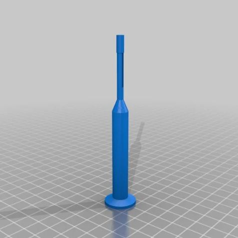
Wire-wrap tool model by [KidSwidden] on Thingiverse.Taking a quick look at the wire-wrap tools available on Thingiverrse, we can see basically two categories: one which goes for minimally viable, with just a cylinder that has a hole poked on the side for the stripped wire to fit through, as these versions by [JLSA_Portfolio], [paulgeneres], [orionids] and [cmellano]. The WSU-30M and similar tools have a channel on the side that the stripped wire is fed into, to prevent it from getting tangled up and snagging. On the clone units this channel often has to be taped off to prevent the wire from escaping and demonstrating why retaining the wire prior to wrapping is a good idea.
This leads us to three examples of a 3D printed wire-wrap tool with such a wire channel: by [KidSwidden] (based on a Radio Shack unit, apparently), another by [DieKatzchen] and an interesting variation by [4sStylZ]. Naturally, the problem with such fine features is that tolerance matter a lot, with an 0.2 mm nozzle (for FDM printers) recommended, and the use of an SLA printer probably a good idea. It’s also hard to say what kind of wire-wrap connection you are going to get, as there are actually two variants: regular and modified.
The starting guide to wire-wrapping by Sparkfun uses the WSU-30M, which as the name suggests uses modified wire-wrap, which means that part of the wire insulation is wrapped around the bottom of the post, for extra mechanical stability, effectively like strain-relief. A lot of such essential details are covered in this [Nuts and Volts] article which provides an invaluable starting guide to wire-wrapping, including detecting bad wraps.
Naturally, the 3D printed tools will not include a stripper for the wire insulation, so you will have to provide this yourself (PSA: using your teeth is not recommended), and none of these 3D models include an unwrap tool, which may or may not be an issue for you, as careful unwrapping allows you to reuse the wire, which can be useful while debugging or reworking a board.
Top image: completed wire-wrap on a post. (Credit: Sparkfun)
When are jumper wires on a breadboard entirely optional? When it’s the latest version of [Kevin Santo Cappuccio]’s Jumperless, which uses a bunch of analog crosspoint switches (typically used for handling things like video signals) to create connections instead of physical wires. There’s even an RGB LED under each hole capable of real-time visualization of signals between components.
If this looks a bit familiar, that’s because an earlier version took second place in the 2023 Hackaday Prize. But things have evolved considerably since then. There are multiple programmable power rails, ADC channels, a rotary encoder, and much more. The PCB design itself is fantastic, including the probe which acts like a multi-function tool for interacting with the whole thing. The newest version will make its debut on Crowd Supply in just a few days.
It’s open source and made to be hackable, so give the GitHub repository a look if you want a closer peek. You can watch it in action in a brief video posted to social media, embedded below.