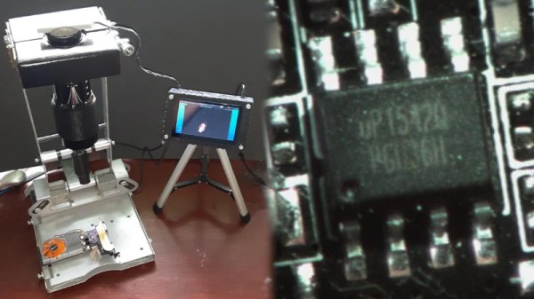
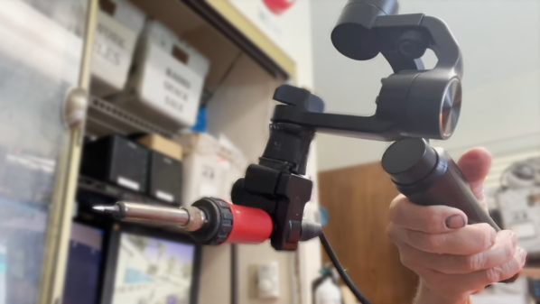
A Hydraulic Bench Vise, Made On The Bench

When we sit down to a build video and see that it’s from [Workshop From Scratch], we know it’ll be a good one, full of plenty of gratuitous metal-wrangling with the promise of an ingenious and useful take on a workshop essential at the end. The home made hydraulic bench vise is the latest from that particular workshop, so settle down with the video below the break for a treat.

Unlike the lead screw we’d expect from a more conventional vise, this one uses a hydraulic pull cylinder and its associated compressor which is powered by compressed air. A substantial vise frame is constructed around the cylinder from thick steel plate, with some careful welding and grinding to ensure a smooth finish.  The result is substantial clamping force with a very smooth and quick action, which doesn’t overhang the edge of the bench in the way a more traditional one does. The hydraulic tube is tucked away through a hole in the bench, and the foot-operated pump lies out of sight on the floor.

Looking at this vise with blacksmith-trained eyes, it raises the question of how it might perform were something in it to be hammered. Overhanging vises are vulnerable to splitting when hammered, so there’s the possibility that this one with its flat mounting might fare a little better. Either way it would be an asset to any workshop.

When it comes to vises, [Workshop From Scratch] is where we saw that magnetic vise earlier last year.

Continue reading “A Hydraulic Bench Vise, Made On The Bench”

AOI By DIY

As anyone who has ever assembled a run of PCBs will tell you, quality inspection of solder joints can be a difficult process. Even under a microscope their appearances can be deceptive, and one silver blob can be perfect while its neighbour conceals a problem. The electronics industry have developed inspection tools to help, including optical inspection devices. It’s one of these that [Sina Roughani] has built, in the form of a hemispherical 3D printed dome with concentric rings of coloured LEDs mounted within it.

The principle behind this tool is as unexpected and simple as it is clever; by having different colours of light from different elevations of the dome it ensures that each different angle of the solder joint surface reflects a different colour. Thus a colour photograph shot from directly above the board allows visual inspection of the quality of the solder joints by the rainbow of colours that appears around their edges. This process can even be automated with OpenCV or similar, hence the process is referred to as Automated Optical Inspection, or AOI.

The technique is demonstrated with some pictures of a Raspberry Pi Pico, on which it shows really well the rainbow-edged solder joints and the red colour reflected from flat pads. What at first might seem like a novelty lighting effect becomes a very useful inspection tool.

PCB inspection is a subject we’ve covered before, though perhaps we don’t all have access to X-rays.

Reverse Engineering USB Protocols On A Function Generator

When working with test equipment such as oscilloscopes and function generators, it can be useful to take a screen capture. Historically this was done with Polaroid cameras that were bolted in place, but these days it can be done over a simple USB connection. [Majenko] didn’t like the Windows-only software that shipped with their Tenma 72-14110 function generator, however, and set about reverse engineering the USB protocol to create their own.

The hack was pulled off by running the original software in a Windows VM, while running Wireshark in the host Linux OS to capture the USB traffic. Once enough data had been captured, [Majenko] set about figuring out how the function generator formatted the screen data when sending it to the PC. Based on the fact that the data changed in length depending on what was on the display, it was surmised that the data was not raw, but compressed somehow. A hunch suggested it was probably some form of Run-Length Encoding, and this proved to be correct. With a little more digging and experimentation, [Majenko] was able to put together some code that netted a clear image from the device.

It’s a useful guide for reverse engineering image data, one that could prove useful if you’re tackling a similar problem on other hardware. We’ve seen some great reverse engineering efforts over the years, on everything from old video hardware to the Sega Saturn. If you’ve been diving deep into the secrets of software or hardware yourself, be sure to drop us a line.

PCB Bath Comes From Russia With Love

[Ruvin Kub] likes magnets, a lot. Most of his projects feature some sort of magnet and his PC board agitation bath is no exception. You can see a video about the device, below. We’ll admit our Russian is pretty rusty, but if you ask YouTube nicely it will translate the Russian subtitles into whatever language you like.

One of the things we liked about the video was that he uses hydrogen peroxide, citric acid, and salt as an etchant. We’ve seen the same mix with vinegar or muriatic acid instead of citric acid. We aren’t sure what the actual  translation is about why he doesn’t like ferric chloride, but YouTube says, “she’s too gloomy for my light souls.”

Continue reading “PCB Bath Comes From Russia With Love”

Using Your Phone As A Microscope On The Electronics Workbench

One aspect of working for Hackaday comes in our regular need to take good quality photographs for publication. I have a semi-decent camera that turns my inept pointing and shooting into passably good images, but sometimes the easiest and quickest way to capture something is to pull out my mobile phone.

It’s a risky step because phone camera modules and lenses are tiny compared to their higher quality cousins, and sometimes the picture that looks good on the phone screen can look awful in a web browser. You quickly learn never to zoom on a mobile phone camera because it’s inevitably a digital zoom that simply delivers grainy interpolated pictures.

That’s not to say that the zoom can’t be useful. Recently I had some unexpected inspiration when using a smartphone camera as a magnifier to read the writing on a chip. I don’t need an archival copy of the image… I just needed a quick magnifying tool. Have I been carrying a capable magnifier for soldering in my pocket or handbag for years without realising it? I decided to give it a try and it worked okay with a few caveats. While I have seen optics turn these cameras into pretty good microscopes, my setup added nothing more than a phone tripod, and will get you by in a pinch.

Continue reading “Using Your Phone As A Microscope On The Electronics Workbench”

Hands On With The Voltera V-One PCB Printer

Creating your own PC board is a rite of passage for many. These days, though, you can order super inexpensive boards and have them in very little time, so it doesn’t always make sense to build your own. Still, some people like the challenge, and others don’t want to wait even a few days. Probably everyone has dreamed of a 3D printer-like machine that would just crank out beautiful PCBs. The Voltera V-One isn’t quite at that level of sophistication, but it isn’t too far from it. [Great Scott] shows us how he built two different boards using the system in the video below. While the results were impressive, you can also see that there are several limitations, especially if you are not designing your board with the machine in mind.

One thing that is obvious is that the machine does need your help. In addition to aligning holes, you’ll need to install tiny rivets for vias and slightly less tiny rivets for through-hole components. The last time we looked at the machine, it didn’t do holes at all, but [Scott] shows the drill attachment which allows the machine to produce vias and support leaded components.

Continue reading “Hands On With The Voltera V-One PCB Printer”

Feeling The KiCad 6 Electricity

In 2018, when KiCad Version 5 modernized the venerable 4.X series, it helped push KiCad to become the stable and productive member of the open source EDA landscape that we know today. It has supported users through board designs both simple and complex, and like a tool whose handle is worn into a perfect grip, it has become familiar and comfortable. For those KiCad users that don’t live on the bleeding edge with nightly builds it may not be obvious that the time of version 6 is nearly upon us, but as we start 2021 it rapidly approaches. Earlier this month [Peter Dalmaris] published a preview of the changes coming version 6 and we have to admit, this is shaping up to be a very substantial release.

Don’t be mistaken, this blog post may be a preview of new KiCad features but the post itself is extensive in its coverage. We haven’t spent time playing with this release yet so we can’t vouch for completeness, but with a printed length of nearly 100 pages it’s hard to imagine [Peter] left anything out! We skimmed through the post to extract a few choice morsels for reproduction here, but obviously take a look at the source if you’re as excited as we are. Continue reading “Feeling The KiCad 6 Electricity”