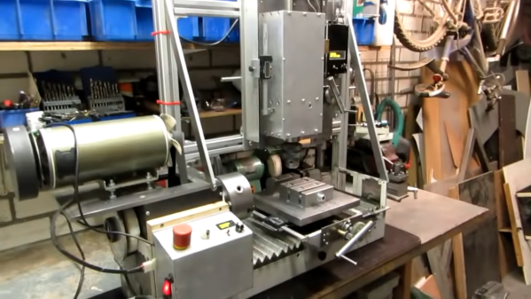
Screwy Math For Super Fine Adjustments: Differential Screws

For any sort of precision machine, precision adjustability is required. For the hacker this usually involves an adjustment screw, where the accuracy is determined by the thread pitch. This was not good enough for [Mark Rehorst] who wanted adjustment down to 10 μm for his 3D printer’s optical end-stop, so he made himself a differential adjustment screw.

Tiny adjustment can be made to the green block due to the thread pitch differences

Differential screws work by having two threads with a slightly different pitch on the same shaft. A nut on each section of thread is prevented from rotating in relation to the other, and when the screw is turned their relative position will change only as much as the difference between the two thread pitches.

The differential screw in this case started life as a normal M5 bolt with a 0.8 mm thread pitch. [Mark] machined and threaded section of the bolt down to a M4 x 0.7 mm thread. This means he can get 0.1 mm (100 μm) of adjustment per full rotation. By turning the bolt 1/10 rotation, the  relative movement comes down to 10 μm.

This mechanism is not new, originating from at least 1817. If you need fine adjustments on a budget, it’s a very elegant way to achieve it and you don’t even need a lathe to make your own. You can partially drill and tap a coupling nut, or make a 3D printed adapter to connect two bolts.

Fabricating precision tools on a budget is challenging but not impossible. We’ve seen some interesting graphite air bearings, as well as a 3D printed microscope with a precision adjustable stage.

Used Soda Stream Cylinder Becomes DIY Canned Air

Soda Stream machines use a cylinder of compressed CO2 to carbonate beverages, and cylinders that are “empty” for the machine’s purposes in fact still have a small amount of gas left in them. User [Graldur] shared a clever design for using up those last gasps from a cylinder by turning it into a makeshift compressed air gun, the kind that can blow crumbs or dust out of inconvenient spots like the inside of a keyboard. It’s 3D printed in PETG with a single seal printed in Ninjaflex.

[Graldur]’s 3D printed assembly screws onto the top of an “empty” cylinder and when the bottom ring is depressed like a trigger, the valve is opened slightly and the escaping gas is diverted through a narrow hole in the front. As a result, it can be used just as you would a can of compressed air. The gas outlet even accommodates the narrow plastic tubes from WD-40 cans (or disposable compressed air cans, for that matter) if more precision is required.

The design is intended for use with nearly-empty cylinders, but even so, [Graldur] also points out that it has been designed such that it can never fully actuate the cylinder’s release valve no matter how hard one presses, so don’t modify things carelessly. We also notice the design keeps the user’s hand and fingers well away from the business end of things.

This device also reminds of somewhat of a past experiment which used 3D printing to create serviceable (albeit low pressure) 3D printed compressed air tanks in custom shapes.

Manual To Hydraulic Press, With A Paint Sprayer

A press can be one of the most useful additions to a workshop, once you have one you will wonder how you ever coped beforehand when it came to all manner of pressing in and pushing out tasks. An arbor press with a big lever and ratchet is very quick to use, while a hydraulic press  gives much higher pressure but is extremely slow. [The Buildist] missed out on an arbor press, so turned his eye to improving the speed of his hydraulic one. The solution came from an unexpected source, an airless paint sprayer that had come his way because its valves were gummed up with paint.

An airless paint sprayer is simply a high pressure pump that supplies paint to a nozzle, and that pump is easily repurposed to pump oil instead of paint. Testing revealed it could produce a pressure of 3000 PSI, which would be plenty to move the hydraulic jack even if the hand pump would be needed to finish the job when higher force was required.

What follows over two videos is a masterclass in hydraulic jacks, as he strips down the jack from his press, and modifies it not only to take an input from the pump, but also to run inverted by the addition of an oil reservoir pick-up pipe. Along the way we learn a few useful gems such as the fact that a grease gun pipe is the same as a hydraulic pipe, but much cheaper.

The result is a jack that extends quickly, and has the pressure to do most pressing tasks without the hand assistance. He crushes a drinks can for effect, then pinches the end of a piece of pipe, because given a press, why wouldn’t you! Take a look at both videos below the break.

Continue reading “Manual To Hydraulic Press, With A Paint Sprayer”

Forming Sheet Metal Parts With 3D Printed Dies

Using 3D printed forms to bend sheet metal isn’t exactly new. We’ve seen several people create custom dies for their brakes, and the results have shown the concept has merit for small-scale production. But that’s usually where the process ends. A bend here or there is one thing, but the ability to form a complex shape with them has always seemed like asking too much. But judging by his recent experiments, [Shane Wighton] is very close to changing that perception.

The process at work here is, relatively speaking, pretty simple. You print out the upper and lower die, put a piece of sheet metal between them, and then smash them together with a hydraulic press. If everything works correctly, and your CAD skills hold true, the metal will take the desired shape.

Of course, that’s vastly oversimplifying things. As [Shane] explains in the video after the break, there are many nuances to forming sheet metal like this that need to be taken into account, and iteration and experimentation are basically unavoidable. So it’s a good thing you can rapidly redesign and reprint the dies.

Which isn’t to say that the dies themselves didn’t come with their own unique set of challenges. The first ones shattered under the pressure, and it took a few design revisions and eventually a switch to a stronger resin before [Shane] got a set of dies that could form the desired piece. Even still, he’s had a lot of trouble getting the printed parts to survive multiple uses. But he’s confident with some more refinements he could get a repeatable process going, and thinks ultimately producing runs of up to 100 parts on a set of printed dies isn’t out of the question.

Logically, it would seem plastic isn’t an ideal choice for punching and shaping metal. Frankly, it’s not. But if you’re doing in-house manufacturing, the ability to produce complex tooling quickly and easily can help make up for any downsides it might have.

Continue reading “Forming Sheet Metal Parts With 3D Printed Dies”

The Best Voltage And Current Reference This Side Of A Test Lab

When you measure a voltage, how do you know that your measurement is correct? Because your multimeter says so, of course! But how can you trust your multimeter to give the right reading? Calibration of instruments is something we often trust blindly without really thinking about, but it’s not always an impossible task only for a high-end test lab. [Petteri Aimonen] had enough need for a calibrated current source to have designed his own, and he’s shared the resulting project for all to see.

The cost of a reference source goes up with the degree of accuracy required, and can stretch into the many millions of dollars if you are seeking the standards of a national metrology institute, but fortunately [Petteri]’s requirements were considerably more modest. 0.02% accuracy would suffice. An Analog Devices precision voltage reference driving a low-offset op-amp with a driver transistor supplies current to a 0.01% precision resistor, resulting in a reference current source fit for his needs. The reference is available in a range of voltages, his chosen 2.048 volts gave a 2.048 mA current sink with a 100 ohm resistor.

In a way it is a miracle of technology that the cheapest digital multimeter on the market can still have a surprisingly good level of calibration thanks to its on-chip bandgap voltage reference, but it never hurts to have a means to check your instruments. Some of us still rather like analogue multimeters, but beware — calibration at the cheaper end of that market can sometimes be lacking.

3D Printed Tooling Punches Above Its Weight With Added Hardware

Reddit user [thetelltalehart] has been making brake press tooling with 3D printed PLA, and recently shared an interesting picture of a hybrid brake press punch, shown here on the right, in blue.

Printed in PLA, with 80% infill and 12 walls, the tool (right) failed at 5 tons.

In a press, material such as sheet metal is formed into a shape by forcing the material around the tooling. Some types of tooling can be 3D printed, and it turns out that printed tools are not only fast and economical, but can be surprisingly resilient. You can see such tools in action in our earlier coverage of this approach here and here.

[Thetelltalehart]’s previous work was printed at 80% infill and 12 walls, and failed at 5 tons. The new hybrid tool adds some common hardware that has the effect of reinforcing the tool for very little added expense or complexity. The new tool made it up to 7 tons before failure. It’s a clever idea, and an apparently effective one.

The goal with these 3D printed tools is twofold: doing short-run work, and reducing costly rework when developing “real” tooling. Having to re-cut a tool because it isn’t quite right in some way is expensive and costly, and it’s much easier and cheaper to go through that process with 3D printing instead of metal.

Don’t Scrape Magnet Wire, Do This Instead

[Tom] doesn’t much like breadboarding. He prefers to wire up prototypes with perfboard and solder point-to-point with enameled magnet wire. That may sound troublesome to some of you, but [Tom] has come up with a few tips to make prototyping with perfboard and magnet wire easier and more effective, and the biggest tip is about how to manage stripping all that magnet wire.

Push the tip of the magnet wire a small distance into the molten solder and hold it there for a few moments. The solder will bubble away the enamel and tin the copper underneath in the process.

Magnet wire is a thin, solid-core conductor that has a clear coating of enamel. This enamel acts as an electrical insulator. The usual way to strip away the enamel and reveal the shiny copper underneath is to scrape it off, but that would get tiresome when working with a lot of connections. [Tom] prefers to “boil it away” with a blob of molten solder on an iron’s tip.

Begin by melting a small amount of solder on the iron, then push the tip of the magnet wire a small distance into the molten solder and hold it there for a few moments. The enamel will bubble away and the solder will tin the copper underneath in the process. The trick is to use fresh solder, and to clean the tip in between applications. You can see him demonstrate this around the 1:00 mark in the video embedded below.

Once the tip of the magnet wire is tinned, it can be soldered as needed. Magnet wire bends well and holds its shape nicely, so routing it and cutting to size isn’t too difficult. [Tom] also suggests a good hands-free PCB holder, and points out that 0603 sized SMT resistors fit nicely between a perfboard’s 0.1″ pads.

Perfboard (and veroboard) have been standbys of prototyping for a long time, but there are still attempts at improving them, usually by allowing one to combine through-hole and surface-mount devices on the same board, but you can see [Tom] demonstrate using magnet wire on plain old perfboard in the video below.

Continue reading “Don’t Scrape Magnet Wire, Do This Instead”