I suppose most of us have had the experience of going to the mailbox and seeing that telltale package in the white plastic bag, the sign that something has just arrived from China. This happened to me the other day, and like many of you it was one of those times when I puzzled to myself: “I wonder what I bought this time?”
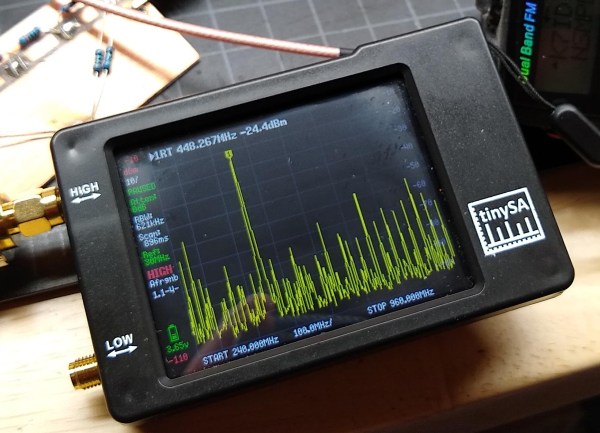
With so many weeks or months between the time of your impulsive click on the “Buy Now” button on AliExpress or eBay and the slow boat from China actually getting the package to your door, it’s easy enough to forget what exactly each package contains. And with the price of goods so low, the tendency to click and forget is all the easier. That’s not necessarily a good thing, but I like surprises as much as the next person, so I was happy to learn that I was now the owner of a tinySA spectrum analyzer. Time for a look at what this little thing can do.
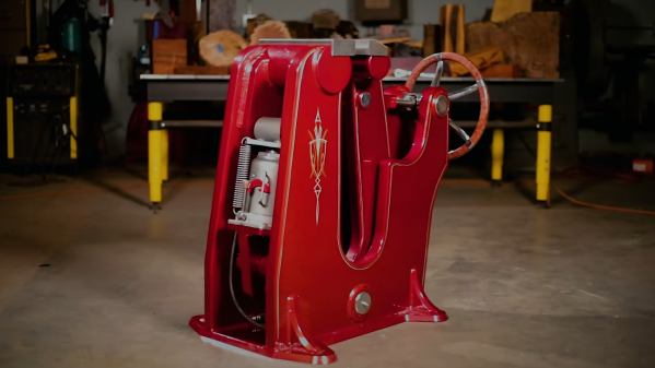
In any proper workshop you want to be able to securely hold a workpiece, whether it’s a tiny PCB or a heavy piece of forged steel. [Jason Marburger] from Fireball Tool needed a really large heavy-duty vise, so he built himself a massive 1490 lbs / 676 kg floor-standing blacksmith vise from scratch.
Blacksmith vises are designed to take a lot of heavy abuse, such as holding heavy pieces of steel that are being hammered. [Jason]’s vise stands about 3 feet tall, and the main frame components were cut from 1 5/8 inch (41.3 mm) steel with a water jet cutter. The jaws are operated with a large hand wheel connected to a lead screw. Bearings on the lead screw allow the hand wheel to be spun like a flywheel, allowing it to be quickly opened and closed. The weight of the moving jaw keeps the lead screw under tension, eliminating any backlash. This allows for really fine control over the holding force, which [Jason] demonstrates by carefully clamping a tiny screw. With the hand wheel alone the vise can exert 12880 lb / 5800 kg, but a hydraulic lift was also added, boosting the force to 30000 lbs. The deep throat allows a large object to be clamped, and the jaws can also be offset to clamp something to the side of the vise.
The vise was beautifully finished with powder coating and pin striping, which will no doubt wear over time if it’s properly used, but the vise itself should last a few lifetimes. While this isn’t something you can really build in a home workshop, it is always inspiring to see what is possible with a bit more tools, knowledge and skill. The build is documented in a 4 part series (link in first paragraph), but we’ve added a short highlights reel below for your viewing pleasure.
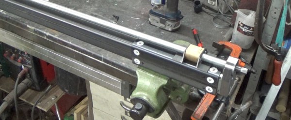
The rise of cost-effective CNC platforms like 3D printers, routers, and laser cutters has gone hand in hand with the availability of affordable and accurate linear rails and extrusions. However, they quickly become expensive when you need something for heavy loads. [Andy Pugh] found himself in need of a large linear slide, so he resorted to making his own with steel square tubing and a bit of PTFE (Teflon).
The PTFE slider/spacers
[Andy] needed a compact motorcycle lift for his small workshop, so he designed one with a single vertical tube that mounts on his floor. The moving part of the lift is a slightly larger tube, onto which the motorcycle mounts. To allow the outer part to slide easily [Andy] machined a set of 16 PTFE spacers to fit between the surfaces of the tubes. The spacers have a small shoulder that lets them mount securely in the outer tube without pushing out. After a bit of fine-tuning with a file, it slides smoothly enough for [Andy]’s purposes. With a large lead screw mounted onto the lift, he can easily lift his 200 kg motorcycle with a cordless drill, without taking up all the floor space required by a traditional motorcycle lift.
Although the Teflon spacers will wear with regular use and, they are more than good enough for the occasional motorcycle service, and are also easy to replace. You may not want to use this on your next CNC machine build, but it is a handy blueprint to keep in your mental toolbox for certain use-cases. These spacers were machined on a lathe, but we found that very similar looking PTFE parts are sold as “wrist pin buttons” for the piston of old air cooled VW engines, and could be modified for the purpose.
For other lifting applications, check out this hydraulic workbench, and this forklift for moving stuff in your crawl space without crawling.
You might think the probes in the picture are just funny looking alligator clips. But if you watch [tomtektest’s] recent video, you’ll learn they are really Kelvin probes. Kelvin probes are a special type of probe for making accurate resistance measurements using four wires and, in fact, the probe’s jaws are electrically isolated from each other.
We liked [Tom’s] advice from his old instructor: you aren’t really ever measuring a resistance. You are measuring a voltage and a current. With a four-wire measurement, one pair of wires carries current to the device under test and the other pair of wires measure the voltage drop.
I’m moving, and in the process of packing all of my belongings into storage boxes to disappear into a darkened room for the next year. Perhaps I could become one of those digital nomads I hear so much about and post my Hackaday stories from a sun-kissed beach while goldfish shoals nibble at my toes. But here in a slightly damp British autumn, box after box of a lifetime’s immersion in tech needs sorting and directing. Why on earth did I hang on to three Philips N1500 VCR system video cassette recorders from the early 1970s! (Don’t worry, those have found a good home.)
Say Hello To An Old Friend Of Mine
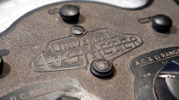
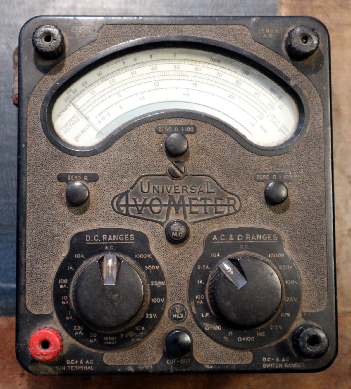
Instantly recognisable, the AVO 8
As I was packing up my bench, I happened upon a multimeter. I have quite a few multimeters and this isn’t the first time I’ve written about these indispensable instruments, but this one’s a little special.
It’s a treasure from my youth, that most venerable of British test equipment: the AVO 8. This was the ubiquitous multimeter to be found in all manner of electrical and electronic workshops across most of the 20th century, and remains to this day one of the highest quality examples of its type.
It’s a relatively huge Bakelite box about 190mm x 170mm x 100mm in size, and it is instantly recognisable by its dual rotary selector switches and the window for viewing the needle, which forms a characteristic circular arc kidney shape.
The earliest ancestors of my meter appeared in the 1920s, and the first model 8 in the early 1950s. Mine is a Mk III that a penciled date on the inside of its meter movement tells me was made in November 1965 and which I bought reconditioned from Stewart of Reading in about 1991, but manufacture continued until the last Mk VIII rolled off the production line in 2008. It’s to my shame that my AVO is a bit dusty and that maybe I haven’t used it much of late, but as I picked it up all the memories of using it to fix dead TV sets and set up optimistic experiments in radio came flooding back. If there’s one instrument that connects me to the youthful would-be electronic engineer that I once was, then here it is. Continue reading “Ode To An AVO 8 Multimeter”→
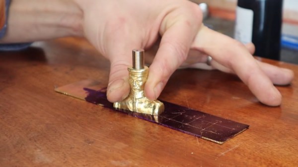
Tired of getting his centerpunches thereabouts but not quite there, [Uri] decided something had to be done. A common tool to solve this problem is the optical centerpunch, but models on sale were just a little too pricy for something so basic. Instead, [Uri] elected to build his own.
An optical centerpunch is a simple tool that helps machinists hit a centerpunch dead on target, time after time. A guide is used that holds a clear plastic rod with a dot in the center. This dot is lined up over the spot to be centerpunched. The plastic rod is then removed and replaced with the actual punch that does the work. Not content to build something utilitarian, [Uri] instead sculpted the tool into a likeness of Sgt Pepper (of Yellow Submarine fame). Seeing the hunk of bare brass quickly become a recognisable figure on camera is a testament to [Uri’s] skill as a sculptor.
It’s a tool that can be readily built by anyone with a lathe, or, at the very least, a decent drill press. We imagine it would be particularly useful for those without perfect vision, making it easier to get punches on the mark on a regular basis. [Uri] has graced these pages before, too — he previously built an ornate tool to make all the other hammers jealous. Video after the break.
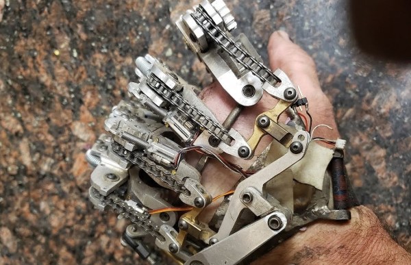
Why aluminum? [Ian] found himself reprinting previous versions’ 3D printed plastic parts multiple times due to damage in the hinged joints, or UV damage rendering them brittle. With an ingenious splaying mechanism and some sensors powered by an Arduino, [Ian] has been wearing the custom machined aluminum hand on a daily basis.
However, as with many makers, he had that itch to revisit and refine the project. Even though the last version was a big jump in quality of life, he still found room for improvement. One particular problem was that the sensors tended to shift around and made it hard to get an accurate reading. To overcome this, [Ian] turned to a molding process. However, adding a stabilizing silicon layer meant that the design of the prosthetic needed to change. With several improvements in mind, [Ian] started the process of creating the plaster positive of his palm, working to create a silicon negative. The next step from here was to create a fiberglass shell that can go over the silicone with sensor wires embedded into the fiberglass shell.
It has been amazing to see the explosion in 3D printed prosthetics over the past few years and hope the trend continues. We look forward to seeing the next steps in [Ian’s] journey towards their ideal prosthetic!