If generations of Hollywood heist films have taught us anything, it’s that knocking off a bank vault is pretty easy. It usually starts with a guy and a stethoscope, but that never works, so the bad guys break out the cutting torch and burn their way in. But knowing how to harness that raw power means you’ve got to learn the basics of oxy-acetylene, and [This Old Tony]’s new video will get your life of crime off on the right foot.
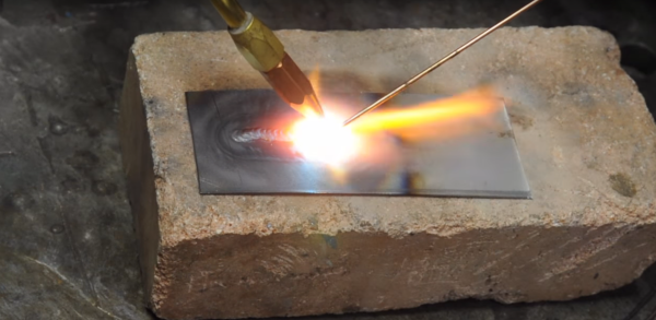
In another well-produced video, [Tony] goes into quite a bit of detail on the mysteries of oxygen and acetylene and how to handle them without blowing yourself up. He starts with a tour of the equipment, including an interesting look at the internals of an acetylene tank — turns out the gas is stored dissolved in acetone in a porous matrix inside the tank. Working up the hoses, he covers the all-important flashback arrestors, the different styles of torches, and even the stoichiometry of hydrocarbon combustion and how adjusting the oxygen flow results in different flame types for different jobs. He shows how oxy-acetylene welding can be the poor man’s TIG, and finally satisfies that destructive urge by slicing through a piece of 3/8″ steel in under six seconds.
We’ve always wanted a decent oxy-acetylene rig, and [Tony] has convinced us that this is yet another must-have for the shop. There’s just so much you can do with them, not least of which is unsticking corroded fasteners. But if a blue wrench is out of your price range and you still want to stick metal together, you’ll want to learn how to braze aluminum with a propane torch.


![This could probably be any of our grandmothers at work. George Grantham Bain Collection [PD], via Wikimedia Commons](https://hackaday.com/wp-content/uploads/2016/10/woman-with-sewing-machine.jpg?w=362)


